Electrical supply project for an apartment building. Power supply of a multi-storey building Input of electricity into an apartment building
Among all existing types of energy that are actively used in modern world In developed countries of our planet, electricity is one of the most popular. Especially important role electricity plays a role in our modern apartment complexes, in which hundreds, and in some of them thousands, of people live.
In this article you will learn:
- What regulations regulate electricity supply? apartment building.
- What is the pattern of power supply?
- What are the advantages of a circular scheme?
- How to connect a house to electrical networks.
- Who should enter into an energy supply agreement with a resource supply organization.
- How to repair old electrical wiring in an apartment building.
Even a short-term loss of electricity can cause significant and serious consequences. That is why the power supply of apartment buildings must be reliable and of high quality, capable of ensuring a non-stop supply of energy to each subscriber. This issue is worked out at the time of building design and is an integral part of the electrical installation process.
What regulations regulate electricity supply in apartment buildings?
The legislation regulating the electricity supply system in MKD is systematically adjusted and is quite extensive. Let's get acquainted with some documentation that is directly related to the issue of power supply.
Market retail electrical energy is regulated by Federal Law dated March 26, 2003 N 35-FZ “On Electric Power Industry”. Conditions for providing utilities for electricity supply in apartment buildings have been adopted by the Rules for the provision of utility services to owners of residential premises and tenants of space in apartment buildings, approved by Decree of the Government of the Russian Federation of May 6, 2011 N 354. In accordance with Regulation No. 1 of these Rules, a permissible stop in the provision of public services and permissible inconsistencies have been established the quality of these utilities to the regulatory GOST 32144-2013, the conditions and process for adjusting the amount of payment for the provided utilities of poor quality and/or with interruptions that exceed the permissible time established at the legislative level.
For example, the possible duration of an interruption in the power supply of an apartment building belonging to the second reliability category (if there are two independent transformers) is 120 minutes, and for apartment buildings that belong to the third reliability category (there is only one transformer) - one day. For each hour that goes beyond the boundaries of the norm established at the legislative level, the amount of payment for utility services for the estimated time is reduced by 0.15% of the amount established for the given settlement period in accordance with Appendix No. 2, taking into account the paragraphs of the ninth section.
Typically, the power supply to MKD occurs through the main distribution board (MSB) or input distribution device (IDU). In this case, all subscribers are powered from a 220/380 V network with a solidly grounded neutral (TN-C-S system). The main switchboard includes a circuit breaker and control devices that allow you to separately disconnect power consumers. The main switchboard distributes power supply voltage to group consumers (lighting of stairwells, basements, attics, elevator equipment, fire and emergency alarms, residential premises, etc.).
Electricity supply to residential premises is carried out through risers, through an RCD. Floor distribution panels are connected to the supply risers, forming a power supply network for the apartments. Floor electrical panels usually include electricity meters, circuit breakers and RCDs. Circuit breakers are grouped for each power supply circuit (lighting, sockets, electric stove, washing machine, etc.). For uniform load on the power distribution network different apartments connected to different phase conductors.

3 power supply diagrams for an apartment building
In order to understand the different power supply schemes of MKD and multi-story building, you should know that the power supply process can be established in different ways, which differ significantly from each other in terms of reliability.
If any transformer or cable is in a faulty condition, the ATS (automatic transfer switch) device will instantly redirect the entire load of the electrical network to a functioning cable. In this regard, problems in the power supply will only be observed for a few seconds. After the electricians arrive at the scene of the accident, electricity will be supplied as normal.
The first category is used for power supply to heating points and elevators in apartment buildings. Typically, this category applies when more than 2,000 people work simultaneously in the same building, as well as in maternity hospitals and intensive care units in hospitals.
Second The reliability category has a number of similarities with the first. When using it, the building is also powered by two cables that have their own transformer. But, if an emergency occurs and technical equipment fails, the entire load will be redistributed to a working cable manually. The specialists on duty are responsible for this. Due to this feature, power outages can last for several minutes.
In addition, this category also includes those houses that consist of nine or more apartments in which electric stoves are installed.
All buildings that belong to this reliability category can be divided into two groups. Each building belonging to this reliability group has two transformers and two power cables. But only in one case, in standard mode, the load is distributed equally between the two cables, that is, evenly.
In the event of an emergency, all electricity network subscribers are redirected to one working transformer until workers fix the faulty one. In another situation, in standard mode, electricity is supplied only through one transformer. And if an emergency occurs, the voltage is immediately switched to the backup (second) transformer.
The simplest category of reliability is third category. In it, the MKD is connected to the transformer using only one cable. The backup cable and transformer simply do not exist. It is for this reason that at the time of an accident a building can be left without electricity for 24 hours. In this regard, it is advisable to have a backup option for autonomous power supply in an apartment building.
Established standards assume that this reliability category includes those buildings whose height is less than five floors, and whose residential premises are equipped with gas stoves. In addition, this also includes buildings with only eight apartments or even fewer if they are equipped with electric stoves. Also included in this reliability category are the houses of gardening associations.
Ring diagram of power supply for an apartment building
Ring power supply diagram for an apartment building - a plan for installing and connecting electrical receivers, according to which power supply to an apartment building is possible via two cable lines forming a ring.
This ring diagram looks like this:

The first and last electrical receivers are connected from the main power source, and so-called jumpers are created between all remaining electrical receivers.
To create such a ring plan, two changeover switches should be provided in the ASU for each apartment building.

Operating mode diagram
In normal mode, the power is evenly divided between the two inputs.
In order to understand why this circuit requires exactly two switches, we let you consider a number of possible emergency situations:
- Failure of one of the supply cable lines
In such a situation, the power supply to all multi-apartment residential buildings comes from one cable line. Specialists from the management company install the switches in the required position.

- Jumper failure

Workers are required to isolate from the power supply circuit the area where the accident occurred (for example, a short circuit occurred on the line). One part of the houses is powered by one cable line, and the second part of the residential buildings is powered by another.
Instead of two changeover switches, you can use three regular ones.
Z Why do you need a power supply project for an apartment building?
Regardless of the moment which reliability category was chosen for the power supply system in an apartment building, its installation can begin only after the power supply project has been formed and signed. Some ordinary citizens cannot understand why this power supply project in an apartment building is needed. After all, as a rule, several weeks are spent on the formation of this project, and the service of its preparation costs a lot of money. But you can’t start installation without such a project.
1. Exactly a well-formed project contributes to rapid implementation workflow without stopping to find out any information, find the resources necessary for the process and organize complex calculations.
Seeing a well-designed power supply project, installation workers will be able to quickly understand the entire scheme and carry out their immediate tasks. job responsibilities without being distracted by extraneous issues. Thanks to the project, the system installation process takes place in a minimum period of time.
2. If subsequently it becomes necessary to carry out repair work on the electrical wiring (this procedure, on the advice of specialists, should be carried out once every 20-25 years), detailed plan power supply in an apartment building will allow all repair work to be completed easily and in a short time. Workers, having reviewed the project on paper, can easily navigate the apartment building, causing minimal damage to the walls of the house during the cable replacement procedure.
This will not only allow you to cope with repairs in short term, but also save money.
3. If a serious emergency occurs related to damage to the electrical wiring in an apartment building, the electrician will only need to familiarize himself with the project in order to understand where the key components are located, from which it is necessary to begin checking the entire electrical supply system. In this regard, a minimum amount of time will be spent on repair work.
But the price of an electrical supply project in an apartment building is quite high. And most customers of construction work seriously think about whether there is an urgent need to spend extra financial resources when ordering an electrical supply project? After all, on the Internet there are a sufficient number of sites where you can download projects of all kinds of buildings: from four-story houses to large high-rise buildings with hundreds of classrooms and offices. Using a ready-made power supply project in an apartment building could save several weeks of work and tens or even hundreds of thousands of rubles.
But nevertheless, this cannot be done. The approach to construction work and installation of the power supply system must be the most serious and thorough, and it is simply impossible to save money here. After all, structures may differ not only in height, but also in the number of residential premises or offices.
You should also know which stoves will be installed in the living areas of the house - gas or electric, since this moment seriously affects the operating power of the power supply system.
In addition, the volume of energy consumption is affected by the geographical location, the quality of the heating system and the insulation of the house, whether additional electric heaters are used in the cold season or not.
Naturally, when developing a power supply system in an apartment building, not only the volume of electricity consumption in standard mode is taken into account, but also at times of maximum load on the system. The level of system load depends not only on the time of year, but also on the time of day.
Incorrect calculations can lead to the fact that the power supply system simply cannot withstand the voltage. Quite often this leads to reboots and fires.
Another extreme also has its drawbacks - if when choosing materials an error occurs on the large side and the power supply system in an apartment building has excessively high power, then when purchasing the required amount of electrical cable you will have to overpay a fairly significant amount of money.
Only true experts in their field will be able to calculate the standard and maximum load on the power supply network in an apartment building, select the appropriate technical equipment and materials in order to develop just such a power supply system that will meet the needs of people in an apartment building.
How to connect an apartment building to electrical networks
The process of connecting an apartment building to the city power supply network can also be accompanied by some difficulties. In order to avoid encountering “pitfalls” in this process, it would be useful to learn about the procedure for connecting the MKD to the power grid. The whole process consists of several stages:
- Submit an application to the organization that connects to the electrical networks and also performs further maintenance. At this stage, you will create technical conditions for connecting the building to electricity.
- These technical licensing conditions should be submitted to the organization that is involved in utility network projects in your locality. The employees of this company will be able to create a power supply project that will fully meet your needs and technical conditions. This project must be formalized in accordance with the existing rules established at the legislative level in our state.
- Next, with this electricity supply project, it is necessary to go to the regulatory authorities and, together with representatives of these authorities, agree on this project.
- Based on the approved power supply project, working documents are generated that describe in detail the points contained in this project.
- Then it is developed working documentation, which will describe in detail the principles laid down in this project.
- Next, the working draft, together with the developed documents, is agreed upon with state regulatory organizations.
And only after going through all the above points, the project itself and the documents on it can be used for the electrification of apartment buildings. In order for light to appear in the MKD, a fairly large number of actions must be performed. But the work process for powering the building does not end there.
Who enters into an energy supply contract for an apartment building?
In accordance with the Civil Code of the Russian Federation, an agreement on the electricity supply of an apartment building is one of the types of purchase and sale agreements. This agreement specifies all aspects of the relationship between the management company and the organization that supplies energy resources, heat and gas to the apartment building. In order to agree on cooperation between the management company and the resource supplier for each type of resource, a separate agreement is drawn up.
If we specifically discuss an energy supply agreement, then at the time of its formation all aspects of the supply of a specific resource - energy - are discussed. The agreement implies the presence of certain conditions, taking into account the specifics of the supply of electricity through the connected network.
An electricity supply agreement in an apartment building establishes the relationship for supplying consumers with electricity through the connected network. This agreement concerns only electricity; nothing is said in this agreement about the supply of other resources (clause 1 of Article 539 Civil Code RF).
Examining the energy supply agreement, we can notice that at its core it consists of information about the parties to the legal relationship and their obligations to each other. This agreement necessarily stipulates the presence of a subject consuming this type of resource, that is, we are talking about a specific owner of a residential premises, to whose address the electricity supply organization will supply this resource (clause 1 of Article 539 of the Civil Code of the Russian Federation).
It is also necessary to say that, in addition to this agreement, which the supplying company signs with the electricity consumer, there are other agreements, that is, agreements that are drawn up between energy systems and companies involved in the production of this resource (electricity).
These agreements do not relate to the specific supply of electricity to the owner of a residential premises, but establish at the legal level the relationship between energy systems and block stations for the organization of a continuous flow of electricity.
If the agreement drawn up between the organization-supplier and the consumer of electricity specifies the obligations of the organization-supplier to supply the owner of the residential premises (subscriber) with electricity through the connected network and the obligations of the consumer to systematically pay for the consumed resource, then this agreement can be considered valid.
In addition to all of the above, the agreement also stipulates the consumer’s obligations to comply with the resource consumption regime, guarantees safe use energy networks and control over the serviceability of electricity metering devices (Article 539 of the Civil Code of the Russian Federation).
According to the law, an electricity supply contract is considered mutual, compensated and of a public nature. This legally executed document must be concluded between the two parties (Article 426 of the Civil Code of the Russian Federation).
The main provisions covered in the electricity supply agreement are:
- In what volume will this resource be supplied? What should its quality be?
- What is the time period for delivery? What are its time limits?
- What is the value of this resource?
- Requirements for the safe operation of energy networks are discussed, technical equipment and electrical appliances.
Each utility resource that is supplied to the owners of residential premises has certain, unique features. If we talk about electricity, then this type of resource has quite specific characteristics, thanks to which energy can take part in the production useful work. It provides the ability to carry out technological operations, and also helps to develop almost all types of activities, including business.
The physical properties of energy also require specific obligations in the electricity supply contract between the supply company and the consumer. We are talking about the following points:
- detection of a given resource (availability of energy) in its consumption;
- Finding out whether energy is present in power systems is possible only with the help of specific technical equipment;
- fulfillment of the necessary conditions for the safe supply and consumption of this resource.
In the modern world, due to progress in the field of technical equipment for the production, transmission and consumption of electricity, the opportunity has arisen to become involved in the process of circulation of this resource.
Energy by its nature is a resource that is difficult to accumulate in one specific place. Even such rapid technological progress of our time could not solve this problem.
At the moment of supplying electricity to its direct consumer, the supplying company must seriously respond to changes in the volume of resource consumed by subscribers over a certain time interval. In no case should we ignore the dependence of the volume and quality of the supplied resource on the actions of some subscribers in relation to others.
Among the key features of an electricity supply agreement, there is no consideration of the special characteristics of the product. And since energy is a resource that itself has a number of specific characteristics, an agreement for its supply can only be a purchase and sale agreement.
This electricity supply contract in an apartment building is concluded between two parties, that is, its preparation requires two companies or their representatives, which on the one hand are consumers/subscribers of this resource.
The second party to the agreement is the company organizing the supply of electricity to the consumer. As a rule, the supplier is a commercial company that either independently produces this resource or purchases electricity and delivers it to the end consumer. Consumers can be both individuals and legal entities.
The supplying company may agree to transfer the supplied electricity to another consumer. This situation is necessarily discussed when signing an energy saving agreement, that is, in the supplier-consumer chain, another party appears - a sub-subscriber (Article 545 of the Civil Code of the Russian Federation).
A sub-subscriber is a consumer of a resource who, by agreement of the parties, is connected to the power grid of a subscriber who receives electricity from the company that supplies this resource.
When studying relationships of this type, it should be noted that they are confirmed by two agreements. First agreement: energy supply agreement, which is signed between the consumer and the resource supplier company; second agreement: an agreement for the use of electricity, which is signed between the consumer and the sub-subscriber. As can be seen from the description, this scheme is quite complex.
Despite the fact that a sub-subscriber appears in the chain, all obligations to the supplying company are assumed by the subscriber who appears in the energy saving agreement.
For a sub-subscriber, the company supplying the resource is the subscriber. In a situation where the mode of delivery of a resource, the level of its quality or volume is violated, then the consumer is responsible to the subsubscriber. But if the parties who enter into an agreement on the supply of a resource come to a common opinion, then they have the right to adjust the agreement and make changes to it regarding obligations to each other.
Both individuals and legal entities can consume this resource. In a situation where a resource supplier company enters into an agreement with an individual, the company can significantly simplify the procedure for concluding this agreement. To recognize the agreement as valid, it is necessary to organize the first connection of the subscriber to an existing connected network (clause 1 of Article 540 of the Civil Code of the Russian Federation).
In accordance with Article 428 of the Civil Code of the Russian Federation, an adhesion agreement is considered to be an agreement drawn up between a company that supplies energy resources and an individual. When the parties sign this agreement, they do not discuss the period of its validity.
In a situation where an agreement is drawn up between a resource supplier company and another legal entity, it is necessary to confirm that the legal entity has an energy receiving device that meets all technical standards. The legal entity also confirms the possibility of organizing metering of consumed energy (clause 2 of Article 539 of the Civil Code of the Russian Federation).
All of the above requirements necessary for drawing up a contract are called technical prerequisites.
An agreement between the resource supplier company and the subscriber cannot be signed in a situation where the subscriber does not have a power plant or if it is in poor technical condition.
It is also impossible to sign an agreement in a situation where the consumer does not have an electricity consumption meter. At the same time, the company providing the resource must necessarily consider all requests received by it regarding the conclusion of an agreement with it (Article 426 of the Civil Code of the Russian Federation).
The management company must enter into agreements with resource supplier companies. If this action is ignored, then the management company is obliged to independently provide public services required by consumers (subparagraph “c” of paragraph 49 of the Rules for the provision of public services to citizens).
According to the legislation of our country and the Rules for the provision of utility services to citizens, associations of residential property owners, housing cooperatives and other consumer cooperatives, as well as management companies, are the main users of services and goods provided by utility companies. They are the ones who buy electricity to transmit it to subscribers living in these apartment buildings and residential buildings. Electricity can also be purchased by premises owners themselves who have chosen direct management of apartment buildings.
Energy Saving Agreement - Paid legal document. The management company assumes obligations to provide utility services to the owners living in the apartment building, and it also bears obligations to the supplier company for timely payment of consumed resources.
The management company is the provider of public services, so it independently charges for consumed resources. It also accepts payment for consumed resources from the owners of residential premises.
Expert opinion
Termination or refusal of the contract
S. A. Kirakosyan,
Ph.D. legal Sciences, Associate Professor, independent expert under the Ministry of Justice of Russia for anti-corruption examination of legal acts, partner of the Estok-Consulting company
In the process of preparing the text of the contract, maximum attention must be paid to the conditions for the fulfillment of obligations and liability for non-compliance. At the same time, the process of terminating a contract or refusing it is recorded quite rarely. But no company can be insured against early termination of relations. This process Parting with counterparties can result in serious financial expenses and damage the company’s reputation.
Often in such contracts one can find confusion in terms, confusion between termination and refusal of the contract. For example, lawyers use formulations that differ from those specified in Article 450 of the Civil Code of the Russian Federation.
Phrases included:
- the right to terminate the contract unilaterally;
- the right to unilaterally withdraw from the contract;
- If there is an unconditional right to withdraw from the contract, the counterparty is sent a notice of termination of the contract.
The confusion in these terms can be argued by the fact that the legislation does not quite successfully reflect two concepts (termination and refusal). Example: under the terms of the supply agreement, “the buyer (recipient) has the right to refuse to pay for goods of inadequate quality... until the defects are eliminated” (clause 2 of Article 520 of the Civil Code of the Russian Federation). In this situation, the concept of “refuse” does not mean termination of the contract, but implies suspension of obligations. In paragraph 1 of paragraph 1 of Article 546 of the Civil Code of the Russian Federation, the legislator designates the right of a subscriber (individual) using energy for domestic consumption to terminate the contract unilaterally. In this situation, the concept of “termination” means “refusal of the contract.”
We can also trace the untimely use of concepts in explanatory letters from state authorized bodies.
For example, explaining the right of subscribers to refuse a management agreement, the FAS RF explained that the owners of premises in an apartment building have the right to unilaterally terminate the management agreement for apartment buildings (Letter No. ATs/51348/1 dated December 18, 2013).
The same opinion can be traced in the letter of the Ministry of Construction of the Russian Federation dated April 24, 2015 No. 12258-АЧ/04 in relation to the situation “when the management organization unilaterally, without objective reasons and, without prior notice, terminates the management agreement for an apartment building (correctly, refuses to fulfill the agreement) or actually ceases to perform its duties in relation to such an apartment building.”
It can be concluded that the authorized bodies equate refusal of the contract to termination, using language on unilateral termination of the agreement that does not comply with the law.
The essence of the differences between termination and refusal of the agreement is as follows.
Termination of an agreement it will be possible:
- by agreement of the parties (in the absence of violation of the contract);
- at the request of one of the parties in court (in case of a significant violation of the contract or a significant change in circumstances, as well as in other cases provided for by the Civil Code, other laws or the contract).
For example, Article 619 of the Civil Code of the Russian Federation contains a specific list of violations of the contract by the tenant, in the presence of which the landlord has the right to demand its termination in court. The parties may also establish in the agreement other grounds for early termination lease agreement (paragraph 2 of Article 619 of the Civil Code of the Russian Federation).
The right to unilateral refusal can be established both by law and provided for by contract, if this does not contradict the law and obligations.
Cancellation of the contract- this is a unilateral expression of will, a unilateral withdrawal from the agreement. Such a decision may not be related to a breach of contract and may not depend on the parties. The right to unilateral refusal can be established both by law and provided for by contract, if this does not contradict the law and obligations. The right to unilaterally withdraw from a contract can be exercised without going to court. However, this does not deprive the other party of the right, if necessary (for example, to resolve property consequences), to go to court.
Standards for electricity consumption in residential apartment buildings
Federal Law No. 261-FZ “On energy saving and increasing energy efficiency...” dated November 23, 2009 states that every owner of an apartment building is obliged to install metering devices for the services of a resource supplying organization. At the same time, electricity consumption by apartment owners can be accounted for either at one or several tariffs, depending on the time of day.
If the single-tariff electricity metering system is simple and understandable to everyone, then the multi-tariff system consists in the fact that the day is divided into time intervals, which are called tariff periods. Each such period of electricity consumption has a different final cost for the consumer. During the period of maximum system load, the price of one kW/h is the highest, and at low load it is minimal. This economic method motivates the consumption of electricity during periods when the network load is minimal to ensure uniform electricity consumption throughout the day.
Example: by order of the Office for Regulation of Tariff Plans of the Voronezh Region dated December 21, 2015 No. 63/1, tariffs for different time periods in one day were adopted for owners of residential premises of apartment buildings:

The intervals of time periods of the day are prescribed in Order of the Federal Tariff Service of the Russian Federation dated November 26, 2013 No. 1473-e:
Accounting for two zones(two-tariff electricity metering, day/night):
- “Day” (maximum load zone) - from 7.00 to 23.00;
- “Night” (minimum occupancy zone) - from 23.00 to 7.00.
Accounting for three zones(three-tariff electricity metering):
- day zone “Peak” (maximum load zone) - from 7.00 to 10.00 and from 17.00 to 21.00;
- day zone “Half-peak” (medium load zone) - from 10.00 to 17.00, from 21.00 to 23.00;
- day zone “Night” (minimum load zone) - from 23.00 to 7.00.
In order for the owner of an apartment in an apartment building to understand whether it makes sense for him to switch to multi-tariff metering of electricity consumption, he needs to draw up a monthly schedule of electricity consumption, recording data from the electrical meter at 7.00 and 23.00 for the two-tariff option and at 7.00, 10.00, 17.00, 21.00 and 23.00 - for a three-tariff scheme. Based on the recorded information, it will be possible to calculate electricity consumption for all time periods and understand whether there is a need to switch to multi-tariff electricity metering.
You can also resort to a less labor-intensive method. For example, the average bill for electricity consumption is 800 rubles per month at a single-rate tariff, the cost of one kWh = 3.23 rubles. From these data you can calculate the number of kW/h consumed per month: 800/3.23 = 248 kW/h. In order to calculate the costs for two-tariff metering, assume that half of the electricity consumption occurs during the daytime, and the remaining half at night. In this situation, the costs will be:
124 × 3.71 + 124 × 2.10 = 720.44 rubles per month, that is, the savings will be equal to 79.56 rubles (800 rubles − 720.44 rubles = 79.56 rubles)
However, let’s return to the metering devices that are responsible for accurately recording electricity consumption in apartment buildings. Today, enterprises produce a large number of different modifications of meters. Their key difference is that they have different purposes: for a single-phase or three-phase network. Meters for single-phase networks are used in typical linear networks with a voltage of 220 V, and meters for three-phase networks Designed for networks with a voltage of 380 V.
In addition to the rated voltage, metering devices, according to GOST 31818.11-2012, have other important technical features:
- base current: the value of the current level, which is the initial value for establishing the requirements for an electricity metering device with direct connection;
- rated current: the value of the current level, which is the initial value for establishing the requirements for an metering device operating from a transformer;
- maximum current: the maximum current level at which the metering device meets the accuracy requirements specified in the standard;
- rated frequency: frequency value, which is the initial value when determining the requirements for the metering device;
- accuracy class: a value equal to the limit of the main permissible error, which is expressed in the form of a relative error as a percentage.
The accuracy class of an electricity meter must be at least 2.0 (for residential premises in apartment buildings and groups equivalent to them, for example, for garage-building cooperatives). In apartment buildings connected to power grid facilities after 2012, it is necessary to install house-wide (collective) electricity meters that meet accuracy class 1.0 and higher. For commercial areas (shopping centers, offices, retail outlets, etc.), the conditions in terms of laws are stricter - an electricity meter with an accuracy class of at least 1.0 must be installed.
They produce electricity consumption meters with the following accuracy classes: 2S, 0.5S, 1.0 and 2.0. In the modern world, retail stores offer a huge list of electricity meters, both single-tariff and multi-tariff, from leading manufacturers: Energomera, Incotex, Taipit, Legrand, Schneider Electri, etc. The types of meters from these manufacturers are approved by the executive authority on technical regulation and metrology and are included in the state database of measuring instruments.
Expert opinion
Technological losses are inevitable
V. D. Shcherban,
Chairman of the HOA “Moskovskaya 117”, Kaluga
From time to time, among the owners of apartments in apartment buildings, there are dishonest people who deliberately underestimate electricity consumption figures. Not all owners replace metering devices whose service life has long passed, which leads to serious distortions in energy consumption data.
Each metering device operates independently from electricity and consumes energy. Plus, it has a sensitivity threshold; due to this point, the device simply does not recognize current passing through it below this limit. It should also be said that the older the electricity meter, the rougher its data. I believe that the total monthly measurement error can reach 1.5-3 kW for each metering device, and on older models of metering devices this figure will be even higher. Now try multiplying these values by the number of meters located in one building!
Also, the quality of the electrical cable can affect technical losses. In a multi-storey residential building with major renovations and modern communications, the level of technical losses is much lower. Modern builders use copper cable, while the indoor wiring of old (Soviet) houses still remains aluminum. Cable connections, especially cables made from different materials, have electrical resistance, which involves certain losses. But no one performs this kind of calculation, especially since the apartment owners know nothing about it. But such losses are taken into account by the general building meter.
These subtleties of power supply in an apartment building increase general house expenses, and payment falls on the shoulders of law-abiding residents of such a building and tenants. For example, in an apartment building (60 apartments), almost all electricity meters in the apartments were updated to devices with anti-magnetic stickers. General house electricity costs include: intercom, lighting on stairs, provider equipment, video surveillance systems, automatic gates. For each system in the field common use Your own electricity meter is installed. To save energy on lighting entrances, LED lamps are used, and motion sensors are installed on the first floor of the house. Data from each electricity meter installed in a public place is collected systematically.
In 2015, the electricity consumption in our home looked like this. The monthly standard for electricity consumption for general household needs, adopted according to the Rules for the provision of public services No. 306, is 350 kW per hour. The actual consumed volume for all general house systems during the same time was approximately 220 kW per hour, which is significantly lower than the established standard. The average monthly difference between the level of electricity supply in an apartment building and the level of general house consumption by residents inside residential premises is 660 kW per hour. This figure is almost twice the established standard and three times the actual consumption of general house systems.
50 kW/h were spent on technological losses, and 180 kW/h on losses of apartment metering devices. The result was 450 kW per hour. But where did 210 kW per hour disappear? Experts have not been able to find an answer to this question.
Repair of the electrical supply system of an apartment building
The condition of many apartment buildings is far from up to standard, since most of them were built back in the 50s of the last century. Many of them require major repairs, which include:
- repair of the roof (roof) of the house;
- major renovation electrical wiring;
- installation of electricity, water and heat meters;
- installation of a heating system;
- installation of hot and cold water supply systems;
- repair work, insulation of building facades;
- repair of elevators, etc.
It’s great if your MKD has a fund that annually collects certain funds for holding repair work the building itself and the entrances. This seriously reduces the time required for these procedures.
Electrical wiring in MKD is replaced in several stages. At the very beginning, the building is de-energized, after which the keys to basement given to electricians. Electricians visit each apartment and ask the property owners if they need any additional outlets, or if existing outlets may need to be moved to another location. After this, specialists design a plan for each living space. This is important for the entire process in order to avoid a large number of problems later. After the building is de-energized and all the data for forming a plan diagram has been collected, the electricians begin to act. First, they dismantle the old electrical wiring system, then install a new one.
Usually experienced electricians begin installing a new cable from the ground floor. But first, the lights are installed in the entrances and on the street, and only then the electricians begin work in residential premises. The benefits come from electrical panels installed separately for each apartment. It’s also good that they are located in the entrances.
These electrical panels contain electric meters with three switches. Devices pass through themselves electrical cable. This process allows you to track flows electrical energy and its size for specific time periods.
MAIN DEPARTMENT OF STATE ENERGY SUPERVISION
GUIDANCE MATERIALS
FOR ELECTRIC SUPPLY OF INDIVIDUAL RESIDENTIAL HOUSES, COTTAGES, COUNTRY (GARDEN) HOUSES AND OTHER PRIVATE STRUCTURES
INSTRUCTIONS
ON ELECTRIC SUPPLY OF INDIVIDUAL RESIDENTIAL BUILDINGS AND OTHER PRIVATE STRUCTURES
1. General Provisions
1. General Provisions
1.1. This Instruction was developed in accordance with paragraph 5 of the Resolution of the Council of Ministers - Government of the Russian Federation dated May 12, 1993 No. 447 "On State Energy Supervision in the Russian Federation" and defines additional requirements for the design, installation, admission to operation and operation of electrical installations of individual residential buildings , cottages, country houses, garden houses, garages, sales tents, privately owned by citizens (hereinafter referred to as private property).
1.2. The design of power supply for private property must be carried out in accordance with GOST R 50571.1 "Electrical installations of buildings. Basic provisions", GOST 23274 "Mobile buildings (inventory). Electrical installations. General technical conditions", Rules for the construction of electrical installations (PEU) and other regulatory documents.
1.3. The operation of electrical installations of private property must be carried out in accordance with the requirements of the Rules for the Use of Electrical Energy, the Rules for the Operation of Consumer Electrical Installations, the Safety Rules for the Operation of Consumer Electrical Installations and these Instructions.
1.4. Responsibility for the technical condition and safe operation of electrical installations, electrical wiring, electrical equipment (devices, apparatus, etc.) of private property rests with the individual owner, hereinafter referred to as the consumer.
1.5. The following should be familiarized with the contents of this Instruction: inspectors of the State Energy Supervision Service, employees of energy supply organizations* issuing technical conditions (TU) for connecting private property; consumers applying to Gosenergonadzor or an energy supply organization to obtain permission to supply energy to private property; specialists from design organizations involved in the design of energy supply for private property.
_________________
* Energy supply organization is a legal entity, a specialized enterprise that owns or has full economic control of generating energy sources and (or) an electrical network, and provides consumers with electrical energy on a contractual basis.
2. Technical conditions and design documentation
2.1. To obtain permission to use electricity, the consumer must submit an application to the energy supply organization to whose networks private property is planned to be connected.
The application must indicate:
name of the private property;
location;
design load, kW;
voltage level (0.23; 0.4), kV;
type of input (single-phase, three-phase);
the need to use electricity for heating and hot water supply.
After receiving an application from the consumer, the energy supply organization (energy system networks, city and regional networks utilities, enterprises, organizations, etc.) within two weeks issues technical specifications, which must indicate:
attachment point;
voltage level and coordinated load of the connected private property;
requirements for protection devices, automation, insulation and overvoltage protection;
requirements for estimated electricity metering;
recommendations for attracting a design organization and using standard projects;
the need to obtain permission from the State Energy Supervision authorities to use electricity for heating and hot water supply;
data on the prospects for network development;
recommendations for organizing the operation of an electrical installation.
At the same time, the energy supply organization issuing technical specifications is responsible for their sufficiency in ensuring the possibility of safe operation of electrical installations of private property objects connected to its networks.
Compliance with technical conditions is mandatory for consumers and design organizations developing power supply projects for private property.
2.2. For private property, it is mandatory to carry out a power supply project (with a total installed capacity of more than 10 kW), which must provide solutions for:
external and internal power supply diagram;
internal wiring diagram: type of wires and method of laying them;
diagram of input devices;
calculation of electrical loads;
selection of settings for automatic circuit breakers and fuse links;
grounding or grounding (if necessary);
installation of a residual current device (RCD) at the input (if necessary, at the point of connection of the object to the supply network);
calculated electricity metering.
For private property with a total installed power of less than 10 kW, a design drawing can be made, which should reflect:
diagram of external and internal power supply indicating the types and settings of protective devices, sections and grades of wires, design currents, electricity metering devices, connection to the supply network;
situational plan for the location of electrical equipment, laying of cables, wires, grounding or neutral conductors;
specification of electrical equipment, products and materials;
explanations, instructions, notes (if necessary).
2.3. The power supply project (project drawing) is subject to agreement with the energy supply organization that issued the technical specifications and the local State Energy Supervision Authority.
3. Requirements for the design and installation of electrical installations
3.1. Electrical installations and wiring must be installed in accordance with the requirements of the current PUE, building codes and this Instruction.
Electrical household appliances used on private property must comply with GOST 27570.0 “Safety of household and similar electrical appliances”.
3.2. Entry into the facility should be done through walls in insulated pipes so that water cannot accumulate in the passage and penetrate inside.
Entries may be made through roofs in steel pipes ah (pipe stands). In this case, the design of input devices must comply with the requirements of current normative and technical documentation.
3.3. At facilities located geographically in one place, as a rule, only one electric meter should be installed.
For garden and country houses, it is allowed to install a switching device or fuse in front of the meter to turn it off.
3.4. Three-phase meters must have a seal with a state verifier’s mark on the casing that is no more than 12 months old, single-phase meters must be no more than 2 years old at the time of installation.
If the electric meter is connected via instrument transformers, a fence with a sealing device must be provided to prevent unauthorized persons from accessing the current metering circuits.
3.5. It is recommended to place fuses, circuit breakers, magnetic starters, an electric meter, as well as other protective and starting equipment in a cabinet located in a room without increased danger, in places accessible for maintenance.
3.6. The cabinet must be metal, of rigid construction, eliminating vibration and shaking of the equipment. If the cabinet is placed in areas with increased danger or particularly dangerous in terms of electric shock to people, it must have seals that prevent the penetration of moisture.
3.7. Termination and connection of wires and cables to the equipment must be done inside the cabinet.
3.8. Electrical equipment installed on outdoors, must be of appropriate design and protected from direct contact with moisture, dust, and oils.
3.9. Operation of three-phase electric motors in single-phase mode from a 220 V network is allowed only if there are devices that prevent interference with household television and radio equipment.
3.10. The electrical safety of people both inside the facility and outside must be ensured by a set of electrical protective technical measures, including the use of RCDs both at the point of connection to the owner of the electrical networks and inside the facility, re-grounding of the neutral wire at the air input, grounding of electrical receivers, use of double insulation of the input an object.
Specific solutions to ensure electrical safety must be reflected in the project (project drawing).
For grounding, a separate conductor with a cross-section equal to the phase conductor must be used, laid from the input cabinet (box). This conductor is connected to the neutral conductor of the supply network in front of the meter.
The use of a working neutral conductor for this purpose is prohibited.
3.11. The resistance of the re-grounding electrode at the input is taken in accordance with the PUE, depending on the resistivity of the soil.
3.12. For general lighting of rooms with metal walls (garages, kiosks, tents, etc.), lined inside with non-conductive material, with non-conductive floors and insulated protruding metal parts, it is allowed to use closed lamps with a voltage not exceeding 220 V.
3.13. For general lighting of rooms with metal walls (garages, kiosks, tents, etc.), with non-insulated metal parts or conductive floors, it is necessary to use permanently installed closed lamps with a voltage not exceeding 42 V.
Subject to the implementation of the set of electrical protective measures set out in clause 3.10 of this Instruction, the use of lamps for general lighting with a voltage of 220 V is allowed.
3.14. When using hand-held lamps in high-risk or particularly dangerous areas, a voltage of no higher than 42 V should be used.
3.15. In rooms with increased danger and especially dangerous ones when the installation height of general lighting lamps is less than 2.5 m, it is necessary to use lamps whose design excludes access to the lamp without the use of a special tool.
Lamps with fluorescent lamps rated at 220 V may be installed at a height of less than 2.5 m from the floor, provided that their live parts are not accessible to accidental touch.
4. Approval for operation
4.1. After completing the installation of electrical installations and fulfilling the technical conditions, before applying voltage, the consumer is obliged to carry out tests and measurements and prepare the following technical documentation:
a power supply project (project drawing) agreed upon with the energy supply organization and the local State Energy Supervision Authority;
protocols for testing the insulation of cables, wires and electrical equipment;
protocol for measuring re-grounding resistance (if available);
phase-zero loop resistance measurement protocol;
acts for hidden work of cables (wirings), installation of potential equalizers in bathrooms and showers, installation of grounding devices (if any);
permission to use electricity for heating and hot water supply;
technical passports for power electrical equipment;
a certificate from the owner of the electrical networks that issued the technical conditions regarding their implementation;
an act of delimitation of balance sheet ownership and operational responsibility of the parties (with the exception of private property objects located in housing, garage, dacha-building cooperatives, gardening partnerships);
availability of a certificate for the electrical installation of the facility (the date of introduction will be determined additionally).
4.2. If there are those specified in clause 4.1. documents, the consumer can submit an application for the supply of electricity and call a representative of the local Gosenergonadzor body (energy supplying organization) for:
inspection of completed electrical installations for their compliance with regulatory documents and the project (project drawing);
checking the compliance of the results of the tests and measurements with the standards;
conducting briefings for the owner of electrical installations, which is recorded in the owner’s statement of obligation or in the logbook of individual consumers who have electrical installations above 220 V.
Based on the results of the technical inspection of the electrical installation, an act on the possibility of supplying voltage (permission to operation) is drawn up, which is the basis for issuing a subscription book to the consumer for payments for electricity.
The following are subject to technical inspection and approval for operation of electrical installations by the State Energy Supervision Inspectorate:
private property in rural settlements connected to the power grid;
electric heating and electric heating devices with a power of more than 1.3 kW, regardless of the location of the private property and the source of power supply;
three-phase electrical installations connected to the electrical networks of the power system;
any other electrical installations by decision of the heads of local bodies of State Energy Supervision.
In other cases, inspections and permission to operate private property are carried out by energy supply organizations to whose networks electrical installations are connected.
4.3. The connection of electrical installations of a private property to the electrical network is carried out by the personnel of the energy supply organization that issued the technical specifications.
5. Operation of electrical installations
5.1. The boundary of operational responsibility between the consumer and the energy supply organization for the condition and maintenance of electrical installations is established:
in the case of an air branch - on the first insulators installed on the building or pipe stand;
for cable entry - at the ends of the power cable at the entrance to the building.
Responsibility for the condition of contact connections at the boundary of operational responsibility lies with the energy supply organization.
5.2. If several private property objects have a common external power supply, then the consumer must assume responsibility for operating the external power supply network up to the interface with the energy supply organization.
The separation boundary is established at the entrance to the first object connected to the network of the energy supply organization, or by mutual agreement of the parties.
5.3. The consumer must ensure that their electrical installations are in good working order.
5.4. The consumer is not allowed to connect an electrical load in excess of what is permitted in the technical specifications, as well as to increase the rated current values of fuse links and other protective devices determined by the design.
5.5. All electrical equipment must meet the requirements of GOST and be of industrial manufacture.
5.6. Depending on the category of premises, in relation to the danger of electric shock to people, a tool of the appropriate class of protection against electric shock must be used.
Note. In accordance with clause 1.1.13 of the PUE, the areas where outdoor electrical installations are located are equated to especially dangerous premises in relation to the danger of electric shock.
With the entry into force of this Instruction, the “Standard Instructions for the Electricity Supply of Individual Houses and Other Personal Structures,” approved by Gosenergonadzor on January 15, 1980, becomes invalid.
RECOMMENDATIONS FOR ELECTRIC SUPPLY OF INDIVIDUAL RESIDENTIAL HOUSES, COTTAGES, COUNTRY (GARDEN) HOUSES AND OTHER PRIVATE STRUCTURES
1. REQUIREMENTS FOR THE DEVICE AND INSTALLATION OF BRANCHES FROM OVERLINES TO INPUTES, INPUTS AND IN-SITE ELECTRICAL WIRINGS
1.1. Branches from overhead lines to inputs, inputs and intra-facility electrical wiring must be carried out in accordance with the requirements of the PUE, building codes and Instructions.
1.3. In-house electrical wiring should be carried out using insulated wires or cables that allow external installation on an open casing.
The term “in-site” refers to external electrical wiring intended for power supply to outbuildings, greenhouses, pumps and other electrical receivers located on the territory of a personal plot (garden) and fed through the facility’s meter.
1.4. The distance from the branch wires to the ground must be at least: 6 m above the roadway and 3.5 m above pedestrian areas. If it is impossible to maintain the specified distances, it is necessary to install an additional support or pipe support on the building.
The shortest distance from the object input wires, as well as the internal electrical wiring wires, to the ground surface should be at least 2.75 m.
In-house electrical wiring should not cross the roadway of the personal plot.
1.5. The cross-section of the branch wires, depending on the wire material, must be at least (mm):
|
span, m |
||
|
Aluminum |
||
1.6. Entry into the building (from the terminals at the junction of the branch and input wires to the electricity metering point) should be made with an insulated wire or cable with a non-flammable sheath with a cross-section of at least: for aluminum - 4 mm, for copper - 2.5 mm. The cross-section, grades of wires and cables at the input are selected taking into account their purpose and conditions of use in accordance with the PUE (see Appendix 1).
1.7. To ensure reliable insulation and safe operation of inputs made with unprotected insulated wires, semi-solid rubber tubes and porcelain bushings (funnels) must be used (see drawings 1, 2, 7 and 8).
1.8. For a household located geographically in one place (a manor with a personal plot, a summer cottage (garden) plot, etc.), provision should be made for the installation of one meter, installed, as a rule, in a residential building.
1.9. Power supply to electrical receivers located in outbuildings or on the territory of the facility is carried out through an electric meter installed in the house, using insulated wires (cables) of the on-site electrical wiring.
Laying wires in pipes in the ground is not allowed.
Wires and cables of intra-facility electrical wiring, as a rule, are introduced into outbuildings without cutting (see drawings 3 and 4). Selecting brands of wires and cables - see Appendix 1.
1.10. The designs and dimensions of wire (cable) terminals for intra-facility electrical wiring are carried out in accordance with the requirements for inputs.
1.11. The phase wires of the on-site electrical wiring are connected to the electric meter through a disconnecting device (circuit breaker, residual current device, fuses), which provides reliable protection of the on-site electrical wiring from short circuits and overloads (see drawing 13).
1.12. If it is necessary to install several socket or lighting groups in an outbuilding, a group panel is installed at the entrance to the outbuilding.
1.13. The laying of wires PRN, PRGN, APRN of intra-facility electrical wiring is carried out on insulators. The distance between insulators is no more than 6 m, between wires - no less than 100 mm.
1.14. Fastening of AVT, AVTU, SAP, SAP wires and intra-facility electrical wiring cables (see drawings 11 and 12).
1.15. A device for re-grounding the neutral wire at the entrance to the facility, as an important measure to ensure electrical safety, is mandatory on all three-phase inputs (see drawing 6).
The need for a re-grounding device on single-phase inputs is determined in each specific case by the project (project drawing).
2. DESIGN SOLUTIONS FOR INPUT DEVICES
2.1. The designs of inputs to objects proposed by these Recommendations are determined from the conditions required by the Instructions, PUE, building codes and regulations, as well as the material and height of the walls of structures and the purpose of the input.
In contrast to the definition of the concept of “input from an overhead power line” given in the PUE, “input” also includes structural elements that allow you to insert wires into a structure or bring them out.
The designs of the bushings, depending on their design, are shown in drawings 1-4.
2.2. The design of the air inlet into a facility that has electricity metering must contain all the necessary elements to meet the requirements of regulatory documents both in relation to electrical and fire safety, and in relation to ensuring a visible boundary of balance and operational responsibility (insulators, compressors).
When branching from overhead lines with wires AVT, AVTU, SAP, SAP and cables, it is allowed to enter without cutting the wire (cable). In this case, the boundary of operational responsibility passes, in agreement with the energy supply organization, at the input of the input device.
2.3. It is recommended to enter in-house electrical wiring into outbuildings using wires or cables without cutting them, to ensure reliable protection against fire in the premises in the event of poor contact connections at the input located outside the premises.
2.4. The design of the entrance to the room, in cases where it is impossible to provide the required size (2.75 m) to the input wires from the ground surface, provides for the installation of a pipe stand (see drawing 4).
2.5. To ground (ground) the pipe stands, a grounding bolt with a diameter of 8 mm is provided. Grounding is carried out by connecting the pipe to the grounded neutral wire of the branch using a piece of uninsulated wire of grade A16, terminated with a cable lug.
The cable lug is connected to the grounding bolt, and the free end of the conductor is connected by compression to the branch wire (brand AVT, AVTU) or to the neutral core of the cable.
On branches made with grade A wire or insulated wires of grades APRN and SAP, the free end of the neutral wire is terminated with a cable lug (see drawing 5).
When using wires (cables) with copper single-wire conductors on branches, it is allowed to connect the free end of the core of the neutral working wire (cable) of the branch to a grounding bolt without a tip, with the end of the wire (cable) being formed into a ring and secured between two washers.
2.6. To protect objects from fire due to poor contacts at the point where the input wires are connected to the branch wires, it is necessary:
make contact connections only using clamps;
to connect the input wires to the branch wires, after attaching the branch wire to the insulator, a free end is left, to which the input wire is connected with a clamp (compression) (see drawings 1, 5).
Connecting input wires to branch wires in the span is prohibited. Such connections can serve as a source of increased electrical susceptibility to people and animals due to branch wires breaking and falling to the ground due to unreliable contact connections.
2.7. The output of wires from the house for power supply to internal electrical consumers (outbuildings, greenhouses, pumps, etc.) is carried out through a hole in the wall, equipped like an input.
In the case of using electrical household appliances in outbuildings, the intra-facility electrical wiring is made of three wires: phase, neutral and a protective grounding wire, laid directly from the neutral working wire at the input of the input device to the electrical consumer. The cross-section of the neutral protective wire must be equal to the cross-section of the phase wire (see drawing 13).
The installation of disconnecting devices (fuses, circuit breakers) in the circuit of the neutral working wire and the protective grounding wire is prohibited.
2.8. If there are electrical receivers in the facility that need to be grounded, grounding should be done through plug sockets (connectors) with a grounding contact, for which an additional third wire of the same cross-section is laid from the meters to the sockets of the pantographs.
Power supply to stationary single-phase electrical receivers should be carried out using three-wire lines. At the same time, the neutral working and neutral protective conductors should not be connected on the switchboard under one contact clamp (see drawing 13).
2.9. Electrical installation, insulating and other materials used for equipment entering the room must meet the requirements of climatic conditions, voltage and area of application.
2.10. Entries into rooms are recommended to be made through walls in insulating pipes so that water cannot accumulate in the passage and penetrate into the room.
For fire safety purposes, passages for inputs in walls made of wood or other combustible materials must be made in a steel pipe.
Sealing of places where wires and cables enter through walls and pipe supports is carried out in accordance with the requirements of building codes and regulations.
2.11. The placement of clamps (clamps) for connecting the input wire to the neutral wire of the branch and to the grounding wire of the re-grounding is carried out in such a way that in the event of a break in the neutral wire of the branch, the input wire to the house remains connected to the re-grounding (see drawing 5).
2.12. It is recommended to re-ground the neutral wire at the input using a ground electrode consisting of one or more electrodes with a diameter of at least 12 mm or corners with a shelf thickness of at least 4 mm, providing the required resistance depending on the resistivity of the soil.
When using two or more electrodes, round steel with a diameter of 10 mm is used to connect them, placed on the wall of the house to a height of at least 200 mm above the ground surface. The grounding conductor laid along the wall of the house, depending on the material, must have a diameter of at least: steel - 6 mm; copper - 2.5 mm.
3. REQUIREMENTS FOR THE DEVICE AND INSTALLATION OF INTERNAL ELECTRICAL WIRINGS
3.1. Internal electrical wiring must be carried out in accordance with the requirements of the PUE, building codes and Instructions.
3.2. When performing electrical wiring, the brands of wires and cables and the methods of their installation must correspond to the project and be selected depending on the nature of the premises or conditions environment in them in accordance with the recommendations given in Appendix 2.
Basic technical data of wires and cables recommended for use for power supply of individual residential buildings, cottages, country (garden) houses, outbuildings, etc. are given in Appendix 4.
3.3. The cross-section of the current-carrying conductors of wires and cables must be determined by calculation based on the nature and magnitude of the load, in accordance with the current technical rules and standards and should be no less than, mm:
|
aluminum |
||
|
for group and distribution lines |
||
|
for lines to the meter and interfloor risers |
3.4. Open laying of unprotected insulated wires in rooms of individual residential buildings and utility rooms directly on building surfaces and structures, on rollers and insulators in all cases is allowed at a height of at least 2.0 m from the floor.
The height of laying wires (cables) in pipes, as well as cables from the floor level, is not standardized.
The installation height of switches on the wall should be 1.5 m from the floor, plug sockets - 0.8...1.0 m from the floor. Switches and sockets used for open electrical wiring must be installed on pads made of non-conductive material with a thickness of at least 10 mm.
3.5. Can be used in attics the following types electrical wiring: open electrical wiring made with unprotected wires in steel pipes or cables in sheaths made of fireproof or non-combustible materials, laid at any height, and electrical wiring on rollers with single-core unprotected wires, laid at a height of 2.5 m.
Hidden electrical wiring - in walls and ceilings made of fireproof materials - at any height.
Open electrical wiring of attic spaces is carried out using wires and cables with copper conductors.
Wires and cables with aluminum conductors are allowed in attic spaces buildings with fireproof floors, provided they are laid openly in steel pipes or when laid hidden in fireproof walls and ceilings.
3.6. The lines of socket groups from the input (group) panels to the plug sockets must be three-wire (phase, neutral working and neutral protective conductors) and must have cross-sections of zero working and neutral protective conductors equal to the cross-section of phase ones.
There should be no disconnecting devices or fuses in the circuits of zero operating and zero protective conductors.
For electrical receivers that do not have a metal case with two-wire connecting cords and 2-pin plugs, it is allowed to install two-pole sockets with their connection to the phase and neutral working conductor of a three-wire socket line.
The use of existing portable electrical receivers with metal cases, with two-wire connecting cords and 2-pin plugs (irons, kettles, stoves, refrigerators, vacuum cleaners, washing and sewing machines, etc.) is allowed (ensures electrical safety) only if:
the presence of non-conductive floors (parquet, wood, linoleum) in the room (room, kitchen);
devices for insulating fencing (wooden gratings, etc.) of metal water pipes, heating radiators, electrical pipes, sinks, bathtubs and other grounded elements and structures that are within hand reach of electrical receivers.
Power supply to stationary single-phase electrical receivers should be carried out using three-wire lines. In this case, the neutral working and neutral protective conductors should not be connected on the panel under one contact clamp (see drawing 13).
3.7. Places of connections and branches of wires and cables should not experience mechanical stress.
At junctions and branches, the cores of wires and cables must have insulation equivalent to the insulation of the cores of entire sections of these wires and cables.
The insulation of cable cores removed from the termination must be protected from aging (coated with insulating varnish or enclosed in rubber or polyvinyl chloride tubes).
3.8. Connections and branches of wires laid in pipes, with open and hidden wiring, must be made in junction and branch boxes.
The designs of junction and branch boxes must correspond to the installation methods and environmental conditions.
Connections and branches of wires and cables in the attic must be carried out in metal boxes by welding, crimping or using compression.
Where they exit steel pipes, wires must be protected from damage by terminating the pipes with bushings.
3.9. Open wiring must be laid taking into account the architectural lines of the premises (eaves, baseboards, corners, etc.).
3.10. The length of wires in damp, damp and especially damp rooms (in toilets, bathrooms, saunas, etc.) should be kept to a minimum. It is recommended to place conductors outside these rooms, and lamps on the wall closest to the wiring. In bathrooms, showers, saunas and toilets, the housings of lamps with incandescent lamps and sockets must be made of insulating material.
Installation of sockets and switches in bathrooms, showers and saunas is not allowed.
3.11. Hidden wiring on heated surfaces (chimneys, hogs, etc.) is not allowed. When wiring is open in the area of hot pipelines, chimneys, etc. The ambient temperature should not exceed 35°C.
3.12. Wiring installed behind non-passable suspended ceilings and cladding walls is considered hidden. They are performed behind ceilings and walls made of combustible materials in metal pipes. In this case, it must be possible to replace wires and cables.
3.13. Fastening the wires with metal brackets must be done with insulating gaskets (see drawings 14, 17).
Metal brackets for securing protected wires, cables and steel pipes must be painted or have another corrosion-resistant coating.
3.14. Wires laid hidden must have a margin of at least 50 mm at the connection points in branch boxes and at the points of connection to lamps, switches and plug sockets. Devices installed hidden must be enclosed in boxes. Branch boxes and boxes for switches and sockets when laying hidden wires must be recessed into the building elements flush with the final finished external surface.
3.15. Hooks and brackets with insulators are fixed only in the main material of the walls, and rollers for wires with a cross-section of up to 4 mm inclusive can be fixed on plaster or in the cladding of wooden buildings.
3.16. Rollers and insulators in the corners of rooms are installed at a distance from ceilings or adjacent walls equal to 1.5...2 times the height of the roller or insulator. End rollers or insulators are installed at the same distance from the wall passages.
3.17. Single-core insulated unprotected wires should be tied with soft wire to all rollers or insulators. Tie wire in damp rooms and external wiring must have an anti-corrosion coating. The insulation of the wires in the places where they are tied must be protected from damage by the binding wire (for example, by winding insulating tape around the wire) (see drawing 19).
Fastening of unprotected wires to rollers or insulators (with the exception of corner and end wires) can also be done using rings and a cord made of light-resistant plastic (polyvinyl chloride). Branching wires are carried out on rollers or insulators.
3.18. When unprotected insulated wires intersect each other, laid at distances from one another less than permissible for the largest cross-section of the intersecting lines, an uncut insulating tube or the wires of one of the lines must be placed and secured on each of the wires of one of the intersecting lines, in order to avoid movement. laid in a groove in the insulating pipes (see drawing 19).
The intersection of flat and solid wires laid directly together should be avoided. If such a crossing is necessary, the insulation of the wire at the intersection must be reinforced with three to four layers of rubberized or polyvinyl chloride adhesive tape.
3.19. The passage through the walls of unprotected insulated wires is carried out in uncut insulating semi-solid tubes, which must be terminated in dry rooms with insulating sleeves, and in damp rooms when exiting outside - with funnels.
When passing wires from one dry room to another, all wires of one line may be laid in one insulating pipe.
When passing wires from a dry room to a damp one, from a damp room to another damp one, and when leaving a room outside, each wire must be laid in a separate insulating tube. When passing wires into a damp room with a different temperature, humidity, etc. funnels must be filled on both sides with an insulating compound. When wires exit from a dry room into a damp room or outside the building, the wire connections must be made in a dry room.
3.20. The passage of protected and unprotected wires and cables through interfloor ceilings must be carried out in pipes or openings.
Passage through interfloor ceilings with twisted wires is prohibited.
The passage of wires through interfloor ceilings may be carried out in insulating pipes in the wall under the plaster. Insulating pipes must be sealed flush with the outer edges of the bushings and funnels.
3.21. The bending radii of unprotected insulated single-core wires must be at least three times the outer diameter of the wire.
3.22. To control lighting, single-pole switches are used, which should be installed in the phase wire circuit.
It is recommended to install switches on the wall near the doors on the side door handle. They can be installed under the ceiling when controlled using a cord.
3.23. Devices installed in damp, particularly damp and particularly damp rooms with a chemically active environment must be protected from environmental influences and have a design that meets the environmental conditions.
4. RECOMMENDATIONS FOR ELECTRICAL WIRING IN INDIVIDUAL RESIDENTIAL BUILDINGS AND OUTDOOR BUILDINGS
4.1. The methods for laying internal electrical wiring given in Appendix 2 are compiled in accordance with the requirements of the PUE, comply with the current technical specifications for wires and cables and are agreed upon with the State Energy Supervision Inspectorate of the Ministry of Fuel and Energy of Russia.
4.2. Recommendations and instructions apply to internal and on-site electrical wiring of individual residential buildings, cottages, country (garden) houses and household outbuildings. When choosing brands of installation wires (cables) for various types of electrical wiring and installation methods used depending on the nature of the environment, you must be guided by the following general provisions.
4.2.1. In the table (Appendix 2) for each type of wiring and method of its implementation, several brands of wires are indicated, arranged in the order of priority of their recommendations.
4.2.2. When designing and installing, you should generally use the wires listed first.
4.2.3. Wires should, as a rule, be used for their main purpose. For example, wires of the brands PPPV, APPV, AMPPV - for pipeless hidden electrical wiring, APPR - for open wiring, without rollers and insulators, directly on combustible surfaces, PV, APV - for open laying on rollers and insulators, as well as in pipes.
4.2.4. Laying wires in pipes should only be used when other pipeless methods of laying wires cannot be used. It is prohibited to lay wires in pipes in the ground outside buildings.
4.3. When using the table in Appendix 2, you must take into account the following explanations to it (the numbers of the explanations correspond to the numbers of the short footnotes given in the table).
4.3.1. Hidden laying of wires directly on wooden or equivalent combustible walls and surfaces (footnote 1) under a layer of plaster is carried out by laying a layer of sheet asbestos under the wires with a thickness of at least 3 mm or over a mark of plaster with a thickness of at least 5 mm. In this case, asbestos or a plaster strip must be laid on top of the shingles, or the latter must be cut to the width of the asbestos lining; the asbestos or plaster strip must protrude at least 10 mm on each side of the wire (see drawing 15).
4.3.2. Hidden laying of wires directly on combustible structures and surfaces (except for premises for keeping animals) is allowed only in steel pipes (footnote 2). Vinyl plastic pipes must be laid over a layer of sheet asbestos with a thickness of at least 3 mm or along a plaster strip with a thickness of at least 5 mm, protruding from each side of the pipe by at least 10 mm, followed by plastering the pipe with a layer of plaster at least 10 mm thick, with the exception of wiring, made with wires with flame retardant insulation.
4.3.3. In animal housing, the use of steel pipes for hidden wiring is not permitted (footnote 3).
4.4. Open laying of unprotected wires, except for APPR, directly on wooden and similar combustible surfaces is not allowed. If necessary in outbuildings, such laying must be made over a fireproof gasket with a thickness of at least 3 mm. In this case, the width of the gasket should protrude 10 mm on each side of the wire. In this case, wires of the brands PPPV, APPV, AMPPV, PV1, APV can be used.
If in specific conditions it turns out that the premises, according to environmental conditions, belong to several categories, then the brands of wires and methods of laying them must meet the requirements imposed on them in all these categories.
APPENDIX 1. SELECTION OF WIRES AND CABLES
SELECTION OF WIRES AND CABLES
Selection of wires (cables) for branching from the overhead line to the input
|
to 2-wire input |
to 4-wire input |
|||
|
Section, mm |
Section, mm |
|||
|
Through the wall and |
PRN, PRGN |
PRN, PRGN |
||
|
pipe stand |
||||
|
AVT, AVTU |
AVT, AVTU |
|||
|
NRG, VVG, VRG |
NRG, VVG, VRG |
|||
|
ANRG, AVVG, AVRG |
If the payment procedure on the payment system website has not been completed, monetary An error has occurred Payment was not completed due to a technical error, funds from your account | |||
Creating a home electrical project is a labor-intensive process that requires extreme attention to detail and appropriate professional skills. Only our company can bring to life a high-quality project with all your wishes.
Electrical supply of an apartment building
To ensure that the power supply project for a village, apartment building, cottage or other site does not drag on for many years, entrust this matter to us.
We will be happy to provide the following services for you:
- Unmistakable determination of the correct location of sockets, switches, lighting fixtures;
- Drawing up a plan for equipment placement;
- Conducting equipment specifications;
Drawing up single-line electrical diagrams for a power supply project for an apartment building or a small cottage can only be done by a master with solid experience.
Electrical installation work price list 2016 Moscow
Price list for electric installation work includes a whole range of works, including the implementation of a turnkey project of any complexity. The price list for electrical installation work in Moscow and other cities includes:
- Installation and dismantling of wiring;
- Laying cables;
- Connection to the public network;
- Laying television and Internet cables;
- Installation of ventilation;
- Electrical panel installation;
- Connecting lighting fixtures;
- Installation of insulated floors, etc.
Our highly qualified craftsmen will come to you in any locality and complete work even with the most complex tasks.
Our advantages in working on a home electrical project:
With us you will forget about the search problem quality materials and the responsible contractor. Our distinctive features include the provision of:
- Only high quality materials
- Proven Tools
- Highly qualified professional craftsmen
- Possibility of prompt travel to the point
- Established democratic pricing policy.
Our turnkey services imply a comprehensive approach to the implementation of power supply projects for a village, apartment building, cottage or any other populated area.
Electrical installation work price list 2016
As part of the implementation of an individual approach, we carefully approach the preparation of a price list for each client individually, within which you will additionally receive:
- Preparation of necessary documentation for government agencies;
- Connecting complex household appliances;
- Setting up electronics;
- Testing the operation of equipment and electronics;
- Quality guarantee for several years.
We know better than anyone that each project is strictly individual, each power supply project for a separate village or country house, apartment building or separate room has its own strengths and weak sides, every design solution in the house is unique.
House power supply project
We are able to inspect, install or dismantle any electrical supply circuit for apartment buildings, including:
- Multi-storey building with a transformer substation;
- Multi-storey building with two cables of a transformer substation;
- A multi-storey building with two cables of a transformer substation and an automatic transfer switch.
We complete the electrical project accurately and promptly, calculating every detail and, if necessary, discussing it with you. Therefore, you don’t have to worry about the cost of your home electrical project. After all, you will not only control our work, but will also be able to clearly define the budget for the electrical wiring project, beyond which we will not go.
Standard design of a 17-storey residential building
EOM - power electrical equipment, electrical power networks and electrical lighting of an apartment building.
This section of the project examines power electrical equipment, electrical power networks and electrical lighting of an apartment building.
The power supply of the main equipment, in terms of reliability, belongs to category II in accordance with the classification of PUE and the requirements of SP 31.110-2003 and is carried out through two cable inputs from an external supply network with a voltage of ~380/220V AC with a frequency of 50 Hz. Grounding system for ASU type TN-C-S.
The facility's power supply is provided from a 0.4 kV switchgear, a designed free-standing radio substation.
The input-distribution device ASU is powered by two mutually redundant cable lines brand APvzBbShp-1 2x(4x120). The cables are laid in a trench in the ground at a depth of 0.7 m.
To distribute power to power electrical equipment, main and emergency lighting fixtures, the project provides for electrical distribution boards ShchAV, ShchSS, PPN.
To supply power to category I electrical receivers, the project provides for the installation of automatic transfer of reserve.
For electrical receivers of the I category of power supply reliability, according to SP 31.110-2003 tab. 5.1 include:
Light barriers;
Elevator equipment;
Emergency lighting;
CCTV;
Fire warning system;
Dispatch system equipment (ACS);
Security and communication systems;
Pumping stations;
Fire-fighting devices (pressure and smoke removal systems, smoke removal valves, fire extinguishing systems);
Source uninterruptible power supply provides autonomous power supply for at least 1 hour.
Power equipment.
The power supply network for power electrical equipment is carried out with VVGngLS 3x[S] cables, in PVC corrugated pipes on the ceiling, in floor preparation and in metal trays, in wall grooves and cable channels, in accordance with the technological plan for the placement of technological and other equipment.
In the event of a fire, shutdown is provided exhaust ventilation air, by turning off the distribution board of system B1.
Nutrition ventilation unit produced by an independent line from the distribution board B1. The smoke exhaust fans are controlled using control boxes type Y5000 (or similar).
Passenger elevator control panel, supplied complete with equipment.
The operation of the pumps is controlled from control stations included in the pumping units supplied complete with the equipment.
The operation of the light-protecting lights (SLM) is controlled from the control panel included in the installation, supplied complete with the equipment.
Electricity of the net
The power supply network for household and technological sockets is carried out using a VVGngLS 3x2.5 V cable PVC pipes with a diameter of 20 mm.
Sockets are installed on the wall in accordance with the elevations indicated on the plan.
Blue - neutral working conductor (N);
Green - yellow - neutral protective conductor (PE);
Black or other colors - phase conductor.
In accordance with clause 7.1.49 of the PUE, for a three-wire network, install plug sockets with a current of at least 10A with a protective contact, which must have a protective device that automatically closes the sockets when the plug is removed.
Daisy chain connection of a PE conductor is not allowed (PUE 1.7.144).
The PVC pipe must have a fire safety certificate (NPB 246-97).
Electrical equipment and materials used during installation must have a certificate of compliance with Russian Federation standards.
Electric lighting
Electrical lighting of premises is carried out in accordance with SP 52.13330.2011 “Natural and artificial lighting”.
Group networks of working and evacuation lighting are carried out using cable brand VVGng-LS 3x1.5, in PVC pipes on the ceiling.
Group emergency lighting networks are carried out using cable brand VVGng-FRLS 3x1.5, in PVC pipes on the ceiling.
The project provides for a combined lighting system and the following types of artificial lighting: working, emergency (backup and evacuation) and repair. The network voltage for working and emergency lighting is 220V, for repair lighting - 36V.
To accommodate automation and protective equipment for electric lighting, the project provides for the installation of a lighting panel in ShchAO and emergency lighting in ShchAO.
The project uses LED and fluorescent lamps.
The choice of lamps was made in accordance with the purpose of the room and the characteristics of the environment, as well as in accordance with the technical specifications.
In public spaces, emergency lighting fixtures are used for emergency lighting at night.
Switches and switches are installed on the wall on the door handle side at a height of 1000 mm from the floor level.
The project provides for manual (local) lighting control, as well as remote control from the control room. To save electrical energy, it is provided automatic control lighting using motion sensors (on the evacuation stairs) and presence sensors (elevator hall and corridor).
The project provides for the installation of an obstruction lighting system (OBS) on the roof.
Protection against electric shock
To ensure the safety of people, the working documentation provides for all types of protection required by GOST R 50571.1-93 (IEC 364-1-72, IEC 364-2-70) "Electrical installations of buildings. Basic provisions." Protection from direct contact is ensured by the use of double-insulated wires and cables, electrical equipment, devices and lamps with a degree of protection of at least IP20.
All metal parts of electrical equipment not normally energized are metal constructions for installation of electrical equipment, metal electrical wiring pipes are subject to protective grounding in accordance with the requirements of the PUE for networks with a solidly grounded neutral, clause 1.7.76 of the PUE ed. 7.
Protection against indirect contact is carried out by automatically disconnecting the damaged section of the network using overcurrent protection devices and implementing a potential equalization system. To protect against low fault currents, reduced insulation levels, as well as in the event of a break in the neutral protective conductor, a residual current device (RCD) is used.
Electricity metering
Commercial metering of electricity is carried out at the border of the balance sheet in the ASU.
As sensors for input control of electricity, use three-phase electronic meters, transformer-connected type Mercury230 ART02-CN 5-10A, having a telemetric output for connection to ASKUE (the type of meter must be agreed upon additionally with the services).
Lightning protection system
Object classification.
Object type - Multi-apartment residential building. Height 45 m. The project adopted the III category of lightning protection in accordance with SO 153-34.21.122-2003.
III level of protection against direct lightning strikes (DLM) - reliability of protection against DLM 0.90. The complex of designed means includes a device for protection against direct lightning strikes (external lightning protection system - LPS) and a device for protection against secondary effects of lightning (internal LPS).
External lightning protection system
Use as a lightning rod metal mesh, made of galvanized steel wire with a diameter of 8 mm (section 50 sq. mm). Use fittings Art. f8 GOST 5781-82. Place the mesh on a layer of insulation, on top of the roof screed. The cell pitch is no more than 15x15m. Connect the mesh nodes by welding. All metal structures located on the roof (ventilation devices, fire escapes, drainage funnels, fencing, etc.) must be connected to the mesh by welding rods Ø 8 mm; the length of the welds is at least 60 mm. All protruding non-metallic structures should also be protected with wire laid on top along the perimeter of the structure and connected to a lightning protection mesh.
Down conductors are located around the perimeter of the protected object. Use galvanized steel strip 25x4 as down conductors. The location of down conductors is shown on the plans. The down conductors will be connected by horizontal belts at levels +12.00, +27.00 and +39.00m.
The project adopted the reinforcement of a reinforced concrete foundation as a grounding conductor, connected by welding with a 50x4 steel strip in accordance with GOST 103-76. The lightning protection grounding strip is laid around the task, at a depth of at least 0.7 m from the ground surface. The soil is loam with a resistivity of 100 Ohm*m. Length of horizontal grounding conductor D = 115.6 m.
Estimated resistance to current spreading is not more than R=4.0 Ohm;
System material - Steel.
All connections are made by welding. Provide anti-corrosion coating for all open elements of the lightning protection system. To protect the ground loop from soil corrosion, cover its elements bitumen mastic MBR-65 (GOST 15836-79), thickness no more than 0.5 mm.
Connect the lightning protection grounding electrode to the main switch on the ASU.
Protection against secondary effects of lightning.
To protect against the introduction of high potential through external metal communications, they must be connected to the ground electrode of the lightning protection system at the entrance of communications into the building. The connection is made with a steel strip with a section of 40x4 (GOST 103-76).
To protect people in elevator shafts from step and touch stresses that may occur on the floor and lifting equipment, a circuit should be installed in the shafts around said equipment. The contour is made of steel strip 40x4. Perform the contour at the horizon +12.00 +27.00 and +39.00m. To equalize the potentials, connect the metal parts of the frame of the lifting mechanisms to the circuits. Connect the elevator protection circuit to the main protection circuit.
All connections are made by welding.
Provide anti-corrosion coating for all elements of the lightning protection system. To protect the system elements from soil corrosion, cover its elements with bitumen mastic MBR-65 (GOST 15836-79).
Instructions for installing grounding of pipelines:
Ground metal pipelines at the entrance from the building, in places accessible for maintenance. Connect all external metal pipelines to an artificial ground electrode of the external lightning protection system. For connection, use a 40x4 steel strip.
For cast iron sewer pipes, use a clamp outlet made of steel 08Х13. Install the clamps on stripped metal. shine the pipe, followed by treating the joint with technical petroleum jelly.
The fastening units must be made in accordance with the instructions of U-ET-06-89.
The transition resistance of the connection is no more than 0.03 Ohm for each contact.
Coordinate with Mosvodokanal the grounding of the water supply system in accordance with UDC 696.6,066356 clause 542.2.1, clause 542.2.5.
Grounding and potential equalization system.
Use the lightning protection grounding circuit as a repeated grounding conductor.
Use the RE VRU bus as the main bus.
Connect the external ground loop to the GZSh. For connection, use steel strip St.50x4.
The connection is made by welding. For strip steel conductors, weld length 100 mm, height 4 mm. Connections to pipes must be made in accordance with the nodes shown in the drawing or in accordance with the requirements of the standard album series 5.407-11 (“Grounding and grounding of electrical installations”). external connections and paint the external steel connecting conductors with MBR-65 bitumen mastic.
Perform potential equalization according to the diagram (see sheets 41 and 40).
Potential equalization conductors that are not part of the cable should be laid openly, secured to the building structures using metal brackets. Determine the distance between the fasteners during installation. Laying through walls should be done in sleeves with a diameter that allows free passage of the conductor. Concealed installation in fire hazardous, hot, damp rooms is allowed.
List of working drawings of the main set of the EOM brand:
- 1. General information
- 2. Single-line electrical circuit diagram of the input-distribution device ASU
- 3. List of electrical consumers and calculation of electrical loads
- 4. Typical units
- 5. Electrical circuit diagram of a single-line distribution board ShchSS1
- 6. Electrical circuit diagram of a single-line DF distribution board
- 7. Electrical circuit diagram of a single-line distribution board ShchSS3
- 8. Electrical circuit diagram of a single-line distribution board ShchSS2 and Ya5111
- 9. Electrical circuit diagram of a single-line switchboard of a floor switchboard
- 10. Electrical circuit diagram of a single-line switchboard
- 11. Connection diagram of active electricity meters to current transformers
- 12. Electrical circuit diagram of a single-line switchboard for a floor ATS
- 13. Installation diagram. General view of ATS
- 14. Installation diagram. General view of the UERM evacuation staircase
- 15. Electrical circuit for lighting control of the elevator hall and corridors
- 16. Group network of technical lighting. underground
- 17. Group lighting network of the 1st floor
- 18. Group lighting network of 2...17 floors
- 19. Power electrical equipment and group lighting network of the technical floor
- 21. Power electrical equipment. underground
- 22. Power electrical equipment of the 1st floor
- 23. Power electrical equipment 2...17 floors
- 24. Grounding and lightning protection of the building
- 26. Diagram of the main building potential equalization system
- 27. Plan for introducing cables from the trench into the building of 0.4 kV networks (section)
- 28. Plan for introducing cables from the trench into the building of 0.4 kV networks
Electrical circuit diagram of a single-line switchboard of an ASU distribution board
Typical installation units

Electrical circuit diagram of a single-line distribution board ShchSS2 and Ya5111

Connection diagram of active electricity meters to current transformers


General view of the floor distribution device (UERM)

Emergency staircase lighting control

Group lighting network. Technical plan underground


Grounding and lightning protection. Technical plan underground


Diagram of the main building potential equalization system
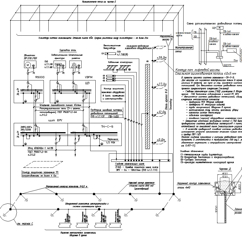
Grounding and lightning protection. Roof plan.
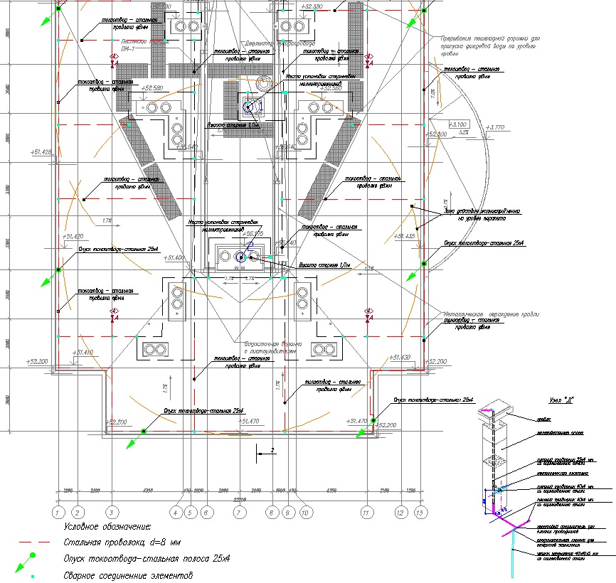
Plan for introducing cables from the trench into the building of 0.4 kV networks
Content:Among the energy carriers actively used by all developed countries, electricity occupies one of the leading places. Particularly important electricity purchases in modern apartment buildings in which hundreds, or even thousands of people live. Even a short-term power failure can cause serious Negative consequences. In this regard, the power supply of an apartment building must be reliable and of high quality, ensuring an uninterrupted supply of electricity to each consumer. This issue is considered at the design stage and is an integral part of electrical installation work.
Categories of power supply reliability
IN multi-storey buildings Different power supply schemes are used, differing in the degree of reliability and methods of supplying electricity to consumers. The first category of reliability is considered the most complex and involves connecting a residential building with two cable lines at once, powered by separate transformers. If a cable or one of the transformers fails, the device will immediately switch all power to the working line. Therefore, the electricity supply will stop for just a few seconds. After repair work, electricity will be supplied as usual again.
In the first category, elevators and heating units of apartment buildings are supplied with electricity. The same category of power supply is selected for buildings in which more than 2 thousand people are simultaneously located. This also includes maternity hospitals and operating rooms in hospitals. This is the most complex circuit power supply of an apartment building.
The second category resembles the first in certain parameters. In this case, the building is powered by two cables connected to its own transformers. However, if the equipment fails, then switching to the working line is carried out by the personnel on duty, and not automatically, as in the first category. As a result, the supply of electricity to consumers may be interrupted for a short time. This power supply option is used in residential buildings over five floors high, equipped with gas stoves. This also applies to houses with nine or more apartments that have electric stoves.

All objects falling under the second category are conditionally divided into two groups. Each of them has two transformers and two power cables. In the first case, when operating in normal mode, the loads are evenly divided between both transformers. In the event of an emergency, all consumers are switched to one transformer until the fault is eliminated. The second option involves using only one transformer, and in the event of an emergency, the voltage supply is switched to the backup transformer.
The simplest category of power supply is considered to be the third, when a residential building is powered from a single cable and transformer. In this case, there is no backup option at all. As a result, in emergency situations, the electricity supply is interrupted for 24 hours. Therefore, it is recommended to think in advance. The third category of reliability includes houses with less than 5 floors, and apartments with gas stoves. This also includes houses with 5 or fewer apartments with installed electric stoves. The third category of electricity supply also includes houses located in gardening associations.
Why is the project needed?
Electrical installation work can only be carried out after the electrical supply project has been drawn up and approved. Project documentation is drawn up in any case, regardless of the reliability category.

Due to the high cost individual project carried out for a specific building, some construction customers prefer to use ready-made solutions that are most suitable for a particular object. This allows you to save significant amounts - from several tens to several hundred thousand rubles. However, such savings in serious construction are completely unacceptable, since all houses differ from each other in their own individual characteristics. Our company’s specialists provide a full range of services and explain the need to perform certain actions.
The main advantages of the project are the following:
- A high-quality project significantly speeds up the completion of work, since all calculations are made in advance and the necessary materials are selected.
- With a ready-made project, installers will understand the entire power supply system much faster and will pay full attention only to their work.
- In the future, when performing electrical wiring repairs, detailed diagram, attached to the project, will make it possible to quickly and efficiently complete all the necessary work. The company’s specialists, after a preliminary study of the power supply plan, will be able to carry out work with minimal damage to walls and other structural elements.
- In the event of an accident caused by damaged wires, the electrician, using the project, can easily identify the key components that need to be checked first. This will again reduce repair time.
The design must take into account the presence of electrical or gas stoves. Electricity consumption will largely depend on this. The company’s specialists will definitely take into account geographical position object, the quality of building insulation and the performance of the heating system. Incorrect calculations can lead to overloads and fires in the electrical wiring. Thus, without drawing up a detailed project, normal power supply to an apartment building is impossible.
Therefore, all calculations, especially those related to normal and peak loads on the electrical network, should only be performed. Only they can do the most optimal choice materials and equipment and create a project that fully meets user needs multi-storey building.
Connecting an apartment building to the network
Connecting an apartment building to the central network is often associated with certain difficulties, mainly due to large losses of time. Therefore, customers turn to our organization to facilitate this process and speed up the power supply to residential buildings.

The company's specialists will do everything necessary work, consisting of several stages:
- Obtaining technical specifications from the organization that performs connection and further maintenance of electrical networks.
- Based on the technical specifications, design documentation for the power supply of the house is developed. In this case, the rules established by current legislation are observed.
- Next, the completed power supply project is agreed upon with regulatory authorities.
- After approval, working documentation is developed with a detailed description of all the main provisions included in the project.
- Then the working design and other documentation are also agreed upon by the regulatory organizations.
After this, the project itself and working documentation can be used for the direct electrification of an apartment building. At the customer's request, all necessary electrical installation work can be performed by the company's specialists. After installation and connection are completed, all necessary checks are carried out to check the functionality of the systems and the correctness of their connection. Based on the results of inspections and tests, reports and other documentation are drawn up. After this, the power supply system can be operated without any restrictions within the installed capacity.