How to disassemble an iron at home. Iron repair: disassembly, typical faults and methods for eliminating them
So, during the ironing process you inserted the plug into the socket, but after a few minutes you realized that the iron was not heating up. In this case, it is not necessary to throw away the equipment and go to the store for a new one, because... Sometimes the cause of a breakdown is quite simple and does not require professional skills in repairing electrical appliances. Next, we will look at what to do if the iron stops heating, as well as how to repair existing damage with your own hands.
Where to begin?
First, you must visually inspect the case for cracks, defects and traces of melting of the case. Maybe appearance will immediately show what exactly is causing the iron to break down. If the inspection does not yield anything, you need to completely disassemble the case to independently diagnose all the components.
Please note that disassembling the iron is sometimes quite difficult. This is due to the fact that every year manufacturers spend more time on the design of electrical appliances, creating invisible fasteners and holes for screws. Initially, prepare a set of screwdrivers and a knife that will be useful to you for further actions.
Video instructions for disassembling the case
Power cord
One of the main malfunctions of the iron is the power cord, which you actually plug into the outlet. 
Get to the junction of the contacts with the heating element and if there are no visible faults, use a tester to ring the cord to determine its functionality. 
For dialing, you can use a wire, consisting of a piece of wire, a battery and a light bulb. If the light comes on when the contacts are connected to both ends of the cord, move on.
If the power cord is the cause of the breakdown, you can try to shorten it by 10-15 cm (perhaps the problem area will be removed). Is your iron still not working? Replace the cord with a new one!
Second in line is the thermostat. We also check it using a continuity tester, which we attach to the contact group.
 When the temperature control is turned toward the circuit closing direction, the electrical circuit should function. Is the light not on? We clean the contacts with sandpaper and check again. We immediately recommend watching the video repair instructions:
How to repair a temperature controller
The thermostat is working, but the iron does not heat up? Let's start checking the thermal fuse!
More often than the power cord, this element of the circuit fails. Its main purpose is to disconnect the electrical circuit if the temperature of the heating element exceeds the nominal value. 
Using a continuity test, we determine the functionality of the fuse. If the reason for the breakdown of the iron is in it, we replace it with a new one, or remove it from the diagram altogether. During normal operation of the temperature controller, there is no need for a fuse.
Heating element (heating element)
Well, the last reason why the iron does not work is the failure of the heating element. If the equipment turns on, the light is on, but the sole does not heat up to the required temperature, most likely this is the problem. As in previous cases, we use a homemade tester to determine the performance of the product. The heating element is attached to the sole and if the attachment point is permanent, then most likely you will have to say goodbye to the purchase (if that is the reason). 
If the heating element is connected to the soleplate using tips, you can try to repair the iron yourself by cleaning the contacts with sandpaper. Still not heating up? We send the equipment for recycling, because... a new part costs almost the full cost of the device!
Please note that if you throw the equipment in the trash, it would be better to disconnect the power cord and keep it for yourself. Perhaps this element will be useful to you in subsequent repairs, especially since it will not take up much space in the closet!
Steaming system
If the malfunction is that the iron’s steamer does not work, then most likely it is necessary to clean the internal steam cavities. To do this, we recommend that you use a solution of water and vinegar in a ratio of 1 liter to 1 glass. Place the sole in a container (as shown in the picture), bring the water to a boil on the stove, turn it off and wait until it cools down. After this, we repeat the action 3 more times, which is enough to properly clean the spray bottle.

In stores you can see special means for cleaning scale, but we strongly do not recommend using them. This is due to the high cost of funds and at the same time low efficiency compared to the folk way! It should also be noted that on thematic forums there are many negative reviews about the fact that the iron does not work after cleaning with salt. This is due to the fact that salt crystals clog the steam supply holes, as a result of which you have to thoroughly clean the sole.
Another reason why the sprinkler does not work is that the steam button is broken. It can also be tested with a tester and replaced if necessary.
That's all the instructions for repairing an iron with your own hands. As you can see, the event is quite simple and even a novice electrician can do it! Finally, I would like to note that if the red indicator on the case is blinking, do not panic, because this may indicate a certain operating mode or automatic shutdown after heating. Read the instructions that come with the kit to understand the reason for the blinking. We hope that now you understand what to do if the soleplate of the iron does not heat up and how to repair the breakdown at home!
Related materials:
If the iron stops heating, you can buy a new one, but often the damage is not very serious and can be repaired yourself. If you know how to use a screwdriver and a multimeter, you can do it. We will talk about how to repair an iron with your own hands in this article.
General device
Since irons are produced by many different companies, they differ slightly - in shape, heating speed, quality of spare parts, etc. But the general structure remains the same. Available:
- Sole with a heating element built into it. If there is a steamer function, there are a number of holes in the sole for steam to escape.
- Thermostat with a handle that allows you to set the required heating temperature for the sole.
- Container/reservoir for water used for steaming.
- There is a nozzle for spraying water and forcing steam out. There is also a steam intensity regulator. With its help, the frequency is set automatic feeding evaporated water.
- The iron is connected to the network using an electrical cord, which is attached to a contact block located in the back under the plastic cover.
General structure of an electric iron
Once you have become familiar with what is where, you can begin repairing the iron yourself.
What will you need for work?
To work, you will need a set of screwdrivers - Phillips and flathead. You will need a wide knife or an unnecessary plastic card to pry off parts of the iron with latches. To check the integrity of the parts you will need a multimeter (read how to use it here). You may also need a soldering iron if you need to change any spare parts.
Tools that may be needed when repairing an iron
All of the tools, but in the process of work sometimes you need electrical tape or heat shrink tubing, sandpaper and pliers may be required.
How to disassemble an iron
The first difficulty faced by those who want to repair the iron themselves is disassembly. This is far from simple and obvious. The easiest way is to remove the back panel. There are several screws that are visible and are not difficult to unscrew. In addition to screws, there may be latches. So, having unscrewed all the visible fasteners, we pry up the cover with the tip of a screwdriver or an old plastic card, and separate the cover from the body.
Underneath there is a terminal block to which the cord is attached. If there are problems with the cord, you can no longer disassemble the iron. But if everything is fine with the cord, you will have to disassemble it further, and this may cause problems.
Some irons - Philips, Tefal - still have bolts under the cover. We also unscrew them. In general, if we see fasteners, we remove them.
Removing the back cover is the first thing to do when disassembling the iron.
How each manufacturer develops its own design, and it often changes from model to model. That is why difficulties arise. But there are several points that are found in almost any manufacturer.
You immediately need to remove the temperature control dial and the steam button, to do this you need to hold them in your fingers and pull them up. The buttons may have latches, so you may need something thin so that you can press them out a little - you can pry them off with a screwdriver.
To disassemble the iron you need to remove the buttons
Some irons, such as the Rowenta, as in the photo, have bolts on the handle (some Scarlet models have them). If there are any, unscrew them. There is also a screw hidden under the removed buttons; we unscrew that too. Then remove the top plastic parts. They are usually secured with snap locks. To make it easier to remove them, you can insert a knife blade or a piece of plastic (plastic card) into the lock.
There are usually a number of bolts under the covers. Having unscrewed them, we continue disassembling until the body and sole are separated. Unfortunately, it is impossible to give more precise recommendations - too different designs there are. What can be advised is to act slowly and carefully. And several videos on how to disassemble irons of different brands.
Power cord
Failure of an electrical cord is a fairly common type of breakdown. With such damage, the iron may not turn on at all or work in fits and starts, and the sole may not heat up well. The cord may bend or curl, the insulation may be damaged at the bends, and some wires may fray completely or partially. If there is such damage, it is better to replace the cord, regardless of whether it is the cause or not. In any case, all places with damaged insulation must be insulated.
In case of any damage, any iron repair begins with checking the cord. To accurately determine whether it is in normal condition or not, you need to ring it. To do this, just remove the back cover. The terminal block to which the cord is connected will become accessible. You will need a tester or multimeter. We put it in the dialing mode, press one probe to one contact of the plug, and touch the second one to one of the wires on the block. When you touch the “correct” wire, the multimeter should make a squeaking sound. This means that the wire is intact.
Checking the integrity of the power cord
The color of the conductor insulation can be any, but yellow-green is necessarily grounding (it must be checked by installing a probe on a small metal plate at the bottom of the plug). The other two are connected to the pins of the plug. One of these two wires should be connected to the pin to which you pressed the multimeter probe. We repeat the same operation with another pin.
To be completely sure that the cord is in good working order, you need to wrinkle/twist it during testing. Especially in places where there are problems with insulation. If the squeak from such actions is interrupted, it is better to replace the cord. It must also be replaced if one or both pins “do not ring.” You may be lucky and you won’t need further repairs to your iron.
Checking the performance of the heating element
If the iron does not heat up at all, the heating element may have burned out. If this is the case, then it is worth buying a new iron, since a replacement will cost almost the same amount. But first of all, you need to make sure that the heating element is to blame.
These are the exits heating element iron
In order to check the heating element, we get to the very sole of the iron. On it, closer to the back, there are two outputs of the heating element. We move the multimeter to the resistance measurement position (up to 1000 Ohms), and take measurements. If the numbers on the display are about 25o Ohm, then the heating element is normal, if more, it’s burned out. As has already been said, if the heating element burns out, it is not worth repairing the iron - it is more profitable to buy a new one.
Checking the thermostat
The thermostat looks like a plate with a group of contacts and a protruding plastic pin, onto which a disk is then placed.
This is the thermostat on the iron
Two contacts fit to the plate. We install multimeter probes on them and check their functionality (call them). In the “off” position, the sound of the multimeter should disappear; when turned on and turned to any position, it should continue to sound.
The damage may be that in the “on” position there is still no contact - then the iron does not heat at all. There may be a different situation - it is not turned off by the regulator and/or does not respond to the position of the regulator. Both reasons are in contacts. And most likely they got burnt.
In the first case, carbon deposits may interfere, which can be cleaned off by inserting a piece between the contacts. sandpaper with fine grain and “slither” along the contacts a couple of times. If you don’t have sandpaper, you can use a nail file, but you need to act carefully - the temperature settings depend on the bending of the plates. So you can’t bend them too much.
In the second case - if the iron does not turn off - the contacts may have become burnt or fused. Repairing the iron in this case consists of trying to separate them. But such a trick rarely succeeds. The solution is to replace it.
Thermostat from a different angle
There may be another point: when falling, the contacts could somehow interlock. When the soleplate of the iron heats up, the bending thermal plate presses on contact groups, but the contacts cannot open. The result is the same - the iron does not turn off when heating. Repairing an iron is also similar - we try to restore mobility to the plates, trying not to bend them. If it doesn’t work, we change it.
Checking the fuse
A thermal fuse is installed approximately in the same area where the thermostat is located. It is used in case the soleplate of the iron overheats - it burns out if the iron heats up to dangerous temperatures. Usually this fuse has a protective tube attached to it and most often it is white.
Iron repair: fuse and its continuity
Find contacts, call. IN in good condition The fuse “rings”; if it’s blown, there’s silence. If you wish, you can move the handset and call directly - there may be a break/burnout in the connecting wire. If a fuse is blown, unsolder it, look for a similar one and install it in place.
There is no need to exclude the thermal fuse from the circuit - it will protect you from a fire in case of problems with the thermostat: it will simply burn out and the iron will not work. And although the iron will require repairs, your home will be safe.
Steam spray system
If almost no steam comes out of the iron, but there is water in the container, most likely the holes are clogged with salts. You can restore functionality with a simple technique. Pour water and vinegar (regular, table) into a bowl with low burs (a frying pan will do). One glass of vinegar per liter of water. The second recipe is for 250 ml of boiling water 2 teaspoons citric acid. Place the switched-off iron into the bowl with the prepared liquid. The liquid should cover the sole.
Cleaning the steam vents on your iron
Place the container with the iron on the fire, bring to a boil, and turn off. Wait until it cools down. Reheat. You can repeat this 3-4 times. Until the salts dissolve.
Sometimes water stops coming out of the sprinkler. This is most likely due to the tube being disconnected. In this case, repairing the iron consists of disassembling the panel on which the injection buttons are attached and installing all the tubes and wires in place.
The second way to descale your iron is to disassemble it completely so that only the soleplate remains. Seal the sole with tape to prevent water from seeping through, but you can also put it in a dish. Pour inside the sole hot water with vinegar or citric acid, let stand until cool, drain, refill. Continue this way until you are satisfied with the result. Then rinse with water and collect.
Similar materials


I love puzzles... especially unexpected ones. This unexpected puzzle “fell on my head” today. More precisely, it fell not on my head, but on my shirt, and it didn’t fall, but fell off.
The iron fell apart in my hands while ironing a shirt... I took it just like that and the sole fell off (it remained hanging on the wires). The problem turned out to be one unscrewed screw (the flimsiness of fastening the soleplate of the iron aroused my suspicions from the very beginning), which secured the soleplate to the “nose” of the iron.
In order to screw this screw into place, it was necessary to disassemble the entire iron, which was a puzzle. A quick Google search did not bring a solution and I had to “assault” the iron... So I decided to combine solving the puzzle with a photo shoot. Maybe it will be useful to someone, although the model of the iron is not known... but still..
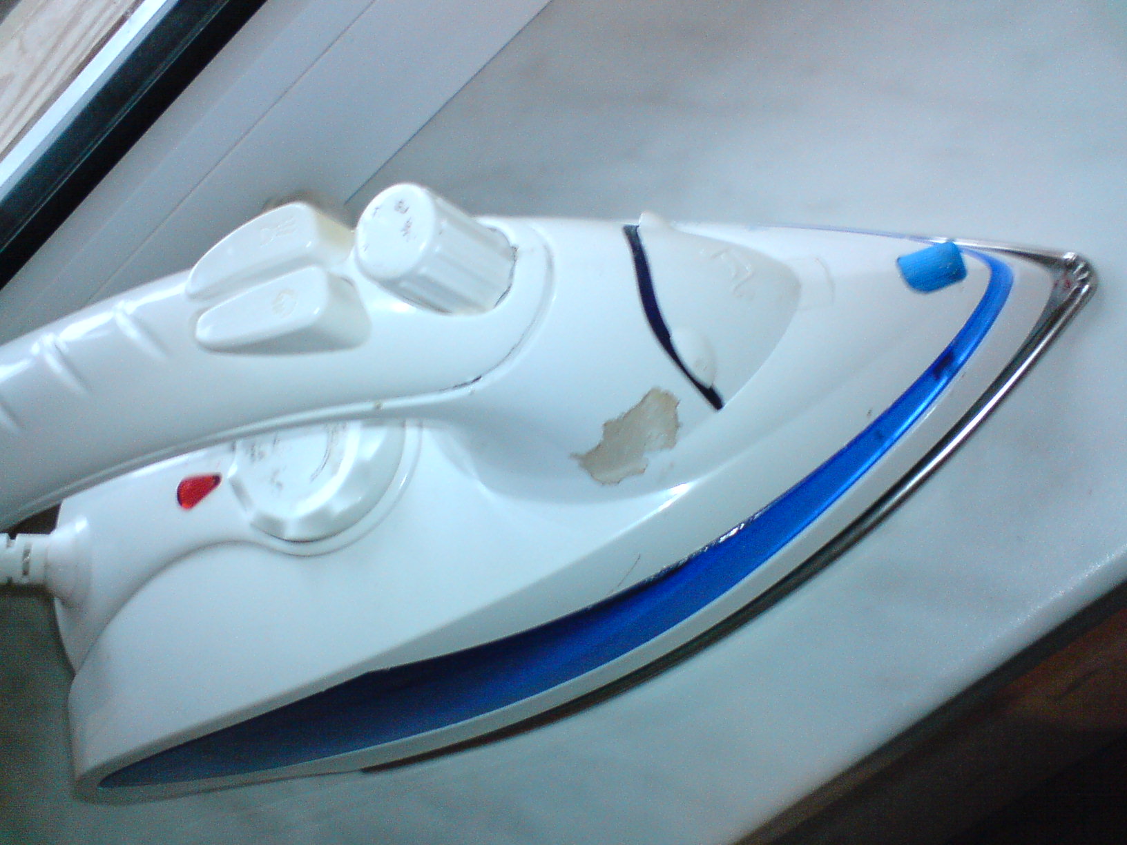
This is what my iron looked like at the very beginning, with the soles falling off and the top of the iron assembled:

The heel of the sole is attached without screws, with some kind of grip-anchors)) That is. the reliability of the design rests on the same screw on the nose of the iron.

Let me note that I took the photographs after disassembling the iron... so what follows will be a “reconstruction of events.”
So meet the iron itself:
Disassembly should begin with the sneaky hidden screw under the lid of the water tank:

But you need to remove the cover from its closed state by hooking it with a screwdriver and lifting it up.
Unscrew the first screw:


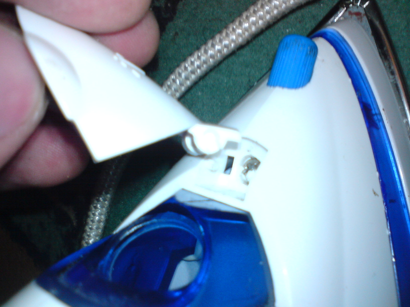
We take out the “horned stuff” from the end of the handle and take out the rotary regulator. To do this, unscrew it counterclockwise until it stops, and then pull it up.

We unscrew this screw, this is the second hidden screw. I found it only when I was assembling the iron... did I break it or was it broken before me (the iron is not mine) will remain a mystery!!! In my case, there is an option to buy super glue or find dichloroethane and glue the plastic together:


The next 2 screws are hidden under the temperature control cover. It will have to be brutally torn out with a screwdriver. (in my case it was easier, I pushed her out inside, because the sole has not yet been screwed on)

Unscrew the screws here and near the heel of the sole. There will be 4 more screws: two large and two smaller...
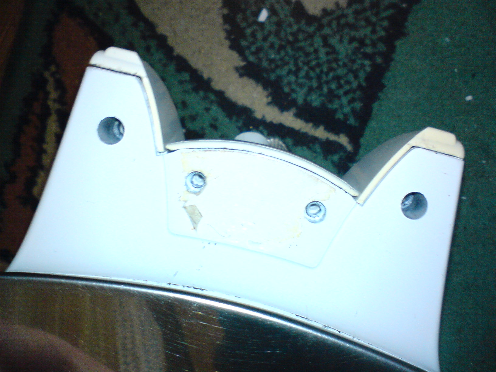
Let's remove the detail:


Mesh filters on the bottom of the cylinders...
You also need to be careful not to tear off (as I did) the tube leading to the sprayer on the nose of the iron:

ALL, I finally got access to the ill-fated screw on the nose of the sole. It can be screwed and assembled iron. But I recommend checking the integrity and tightness of all contacts. And in general, carry out maintenance on the iron, it’s already been disassembled...
When assembling, do not forget to put various little things in place so that there are no “extra parts” left after the repair:
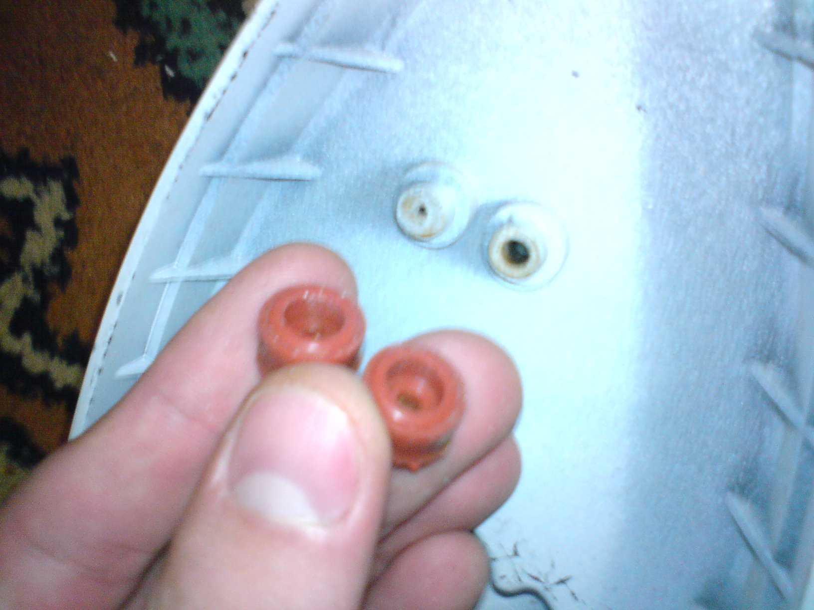
two crap things that I almost forgot to put on. These are some kind of gaskets...
That's it, I tighten the ill-fated screw:

And I begin assembly... in the reverse order of disassembly....
The only thing I will note is that in order to correctly assemble the temperature regulator, I unscrewed it all the way clockwise and accordingly knew in what position the regulator cover itself should be put on... this was the position of the maximum temperature:

Look like that's it…. don’t forget about the screws and don’t get nervous when assembling and disassembling))))
This entry was posted on October 5, 2008 at 13:47 and is filed under with tags . You can follow any responses to this entry through the feed. You can, or from your own site.
Repairing an iron with your own hands is a classic of the household genre, but now, unfortunately, the currents of surrealism are becoming stronger in it. To disassemble a modern iron, a novice master needs to have solving skills Chinese puzzles: Hidden latches everywhere, tricky tenon joints, shaped fasteners. Should I take it to the workshop? The cost of repairs may be such that it is easier to buy a new iron. Let’s still try to fix ours, without professional training and without special tools.
Abstract reasoning
Manufacturers justify turning the iron into a kind of combination lock with safety, design and ergonomic requirements. But, sorry, from the visible fasteners on the irons there were only 1-2 screws at the back, and that remains so. Moreover, the body parts of old irons were made from fragile bakelite and polystyrene, while today’s plastics compete with metals in strength.
In fact, we, alas, live in an age of things that are not eternal. One of the fundamental installations consumer society is inexorable: a product of mass demand must work flawlessly (manufacturer’s reputation, but what) for no more than 2-2.5 warranty periods, and then quickly and irreversibly become completely unusable. Leading manufacturers of consumer goods employ up to half or more of their design personnel to ensure that, God forbid, the product does not turn out to be too durable.
How does the industry's work affect the environment? trash can, and in the mass consciousness - attracting truly high-quality specialists to actually harmful activities is a different question, but the iron almost does not yield to such attempts: it is too simple, and inside it is too hot and humid. Therefore, damage to the iron at the design stage comes down mainly to making it difficult to disassemble it outside the service center. However, it is still possible to repair an iron at home using improvised means if you know where and what secrets may be hidden in it and how to open them without the risk of completely ruining the iron.
Tool
To successfully repair the iron, let's first prepare some homemade instrument; It will not take much time and will not require significant expenses:
- 2-4 lid squeezers;
- squeezer for hidden latches;
- a cheap LED flashlight (namely LED) and a magnifying glass;
- a strip of suede, a nail file, alcohol;
- or, instead of step 4 - a pencil eraser, an ink eraser, a piece of a clean cloth, alcohol.
Note: on the purpose of tools according to paragraphs. 4 and 5 see below.
Push-ups

The lid squeezer is made from the top, strongest layer of bamboo, the size and thickness of an ice cream stick; one end of it is cut into a wedge. The covers on the body of irons are often placed on latches without fixing. At the service center, such a cover is compressed with special pliers and removed. To remove it using a makeshift method, you need to pry off the cover: the teeth of the latches without fixing are beveled on both sides and come out of the grooves intact. But open the lids on tight latches with a table knife or a wide screwdriver, as in Fig. on the right, don’t: the steel will leave marks on the plastic. The flexural strength of the surface layer of bamboo is higher than that of plastics, and the shear strength is lower. Therefore, a bamboo squeezer will remove the lid if it is properly lifted, but perhaps it will be crushed from the surface on its own without damaging the plastic. If the lid is not lifted correctly and does not give in, the bamboo squeezer will break without damaging the iron. They use bamboo squeezers in pairs, prying the part from both sides.
A good thin squeezer for fixed latches is obtained from a plastic coffee stirrer cut into a wedge, which are issued by coffee machines. The squeezer from the stirrer fits into any gap and gently removes the latches with fixation, without scratching or breaking either them or the body parts.
Flashlight and magnifying glass
Cheap mini LED flashlights produce very hard light with harsh shadows. In this case, this is an advantage: such light penetrates deeply into thin cracks, and under a magnifying glass you can see what the part is holding there. To do this, first they pry off the lid, which is not clear how to remove, with bamboo squeezers, highlight it and look at what is holding it there.
How to handle latches
It is best, of course, to find a diagram for disassembling the iron of this model, but try it! AND standard schemes Don’t look for the location of the secret locks either: they can be different for the same model from the same manufacturer. Have you read in the instructions: “The manufacturer reserves the right to make changes to the design that do not affect the performance of the product”? That is, when disassembling the iron, you will most likely have to look for hidden connections yourself.
It must be said that Western companies are gradually moving away from the principle: “Do you want to fix it yourself? Well, break it and buy a new one!” But Asians stubbornly cling to it. For example, if your iron is Chinese, then the nose mounting screw (see below) will most likely be not under the filler cap, but... under the water and steam supply buttons!

Let's light it up and see. Do you see the green circle in the pic? So, this is not a latch, but a sliding tenon in a groove. The latches are on the other side of the buttons. To remove the buttons and disassemble the iron, you need to:
- Push forward button.
- Insert the wringer from the mixer behind it.
- Release the latch.
- Without removing the wringer, lift the button up until it stops. You should hear a faint click of the latch tooth coming out of the groove.
- While holding the button so as not to fall, remove the wringer.
- Continuing to hold the button, move it forward with an inclination so that the sliding tenon turns out of the groove.
- Do the same with the other button.
Shaped fasteners
The screws in irons from Western manufacturers are most often either ordinary with a Phillips or hexagon head. For the latter, there is no point in buying a special screwdriver with a set of bits for a one-time repair: a screw with a hexagonal slot can simply be unscrewed with a flat screwdriver with a thin blade of a suitable width. It can also be used to unscrew screws with a trefoil slot, which the Chinese are very fond of (on the right in the figure), but without strong pressure: this creates a significant lateral force and the screw in the thread can simply jam. If the screw is tight, it is torn off with a series of small jerks, moving the screwdriver to other pairs of slots.

The most difficult thing will be to unscrew the screw with the TORXX slot (on the right in the figure): scissors or tweezers will only take it if the screw is loose in the thread. It is most convenient to unscrew TORXX screws without a special key using small duckbill pliers; You can also use side cutters, but then there will be dents on the slot bridge. They won't do anything to Vintu, but experienced master, suddenly this iron gets to him and charges him for repairs for previous unqualified access.
How does a steam iron work?
But where to look for all these secret screws? To do this, you first need to familiarize yourself with the structure of a modern iron with a steam generator (steamer). Its general diagram is shown in Fig.:

An impact steaming system (with superheated steam) is installed only in certain models, because it is effective only in the thermostat position close to the maximum (three points). In good irons with shock steaming, the shock pump is blocked if the regulator is set to 1-2 points. What is always written about in the instructions, how, pray tell, does a normal housewife read the instructions for an iron? That is, if there is no steam boost, then perhaps to eliminate the “malfunction” you just need to turn the temperature regulator.
The positional protection module turns off the heating element if the position of the sole of the iron differs from horizontal: it was placed upright, dropped, etc. This is perhaps the only electronic innovation in irons. In high-quality irons, positional protection is the second most common source of breakdowns (after scale in the steamer, see at the end), but at home it is most often completely repairable.
How the Chinese soar
If you look at the soles of even cheap Chinese irons, it turns out that many of them have fictitious, fake drip humidification nozzles. In fact, when fully heated steam boost it turns out if you press the steam button; in the same position of the thermostat, soft steam comes from the button with droplets, and for drip humidification in this case you need to press both buttons at once.
Electrical diagram
The electrical circuit of the iron is shown in the following. rice.:

The KM relay and the SK position sensor constitute the position protection. On its board there may be a power indicator, which in this case is LED, and not on the neon. Positional protection can be turned off without compromising the consumer qualities of the iron, but if the indicator is LED, then if the “positioning” is completely turned off, it will stop working. This is inconvenient, so faulty positional protection must be partially disabled (see below).
The numbers with indices show the sequence of testing the “hot” and “cold” circuits with a multimeter: one probe with an alligator clip is connected to the pin of the power plug, and the others go along the points. Both continuities should converge on the contacts of the KM relay. The fact is that the KM contacts are normally open: when the iron is plugged in and the thermostat contacts are closed, the KM pulls, its contacts are closed and current flows through them to the heating element. It is necessary that any malfunction of the positional protection itself disables the heating element (the principle of excess safety), but this circumstance can mislead an inexperienced technician.
Note: when checking, it may turn out that there is a miscontact in the connecting cap, see fig. on right. The only way out is to bite it off and reconnect the wires into a new one.

Thermal protection
The thermal fuse (thermal) is triggered if the temperature of the soleplate of the iron exceeds 240 degrees or the current through the heating element exceeds a certain specified value. That is, the thermal fuse to replace the unsuitable one must also be selected according to the current, depending on the power of the iron:
- 2200 W – 25 A.
- 1500 W – 16 A.
- 1000 W – 10 A.
- 600 W – 6.3 A.
Thermal current redundancy is needed because 220 V is the effective (effective) value of the mains voltage; the amplitude is 220 V x 1.4 = 308 V. The duration of the half-cycle of the frequency 50 Hz is 10 ms, and the thermal response time is 4-5 ms. Suddenly the network voltage jumps to the limit permissible value 245 V, the thermal fuse for the operating current of the heating element can burn out in a perfectly serviceable iron.

Thermal fuses are disposable (pos. 1 in the figure), resettable, pos. 2, and self-healing, pos. 3. The first ones burn out and must be installed in a dielectric heat-resistant sleeve (usually made of fiberglass), otherwise a breakdown of the network voltage at the base is very likely. In a resettable thermal fuse, the prestressed bimetallic strip “snaps” and opens the contacts. To restore it, you need to press it through the window in the contact until it clicks back with something sharp. Self-healing thermal protection will return to its original state if the iron is unplugged and allowed to cool completely. Self-healing thermals are structurally combined with a thermostat (see below) and are always supplemented with a current fuse.
Thermostat
The soleplate temperature regulator is the most important component of the iron and one of the most susceptible to breakdowns; It is a mechanical trigger device driven by a bimetallic plate. There are no “magnets, like in a refrigerator regulator,” in the iron’s thermostat. Like the refrigerator thermostat, there is also a mechanical trigger, only of a different design. The principle of its operation is simple:
- The part with the movable contact is pressed against the fixed one by a reversible spring. The contacts are closed, the heating element is heating up. The degree of compression of the spring is regulated by the temperature setting knob.
- On the other hand, the movable contact is connected by a dielectric pusher rod to a bimetallic plate.
- The bimetallic plate, bending from heat, presses through the rod onto the movable contact until it overpowers the spring.
- The spring is thrown over and opens the contacts.
- The heating element turns off, the sole of the iron with the bimetallic plate cools down.
- The bimetallic strip is straightened. When its pressure weakens sufficiently, the spring is thrown back and returns the regulator to its original state.
The heating element heats up again, the cycle repeats. In old irons and some new ones, the thermostat is assembled according to the scheme with a free rocker arm (item 1 in the figure):

Its disadvantages are 2 pairs of contacts susceptible to burning and large hysteresis, i.e. difference between the response and return temperatures of the regulator. Therefore, in regulators with a free rocker there is always an adjustment screw under the handle, which is turned if the iron heats too much (tighten it by 1-2 turns) or weakly (unscrew it the same amount). To access the calibration screw, you need to remove the temperature control knob. It sits on the axis by friction, but is held in the body by claws with stops, see fig. on right. To remove the handle, you need to turn it all the way to the minimum (at the first point) and pull it up.

Most modern irons are equipped with a unified double-spring thermostat, pos. 2: it works very clearly and almost never requires adjustment during operation. Its weaknesses, firstly, are the same as in the previous one. case, contacts, see below. Secondly, there is a ceramic rod (indicated in blue), which sometimes cracks. The rod length is 8 mm, and a new one can be made from an MLT-0.5 W resistor, pos. 2a. The resistor leads are bitten to a length of 1.5-2 mm, the paint is washed off with dichloroethane or a surfactant remover, and the conductive layer is cleaned off with sandpaper. If the resistance of the resistor is more than 620-680 kOhm, some people install it instead of the rod as is, the paint burns without smoke or stink. However, then the sole of the iron may unpleasantly “pinch” with electricity. And what is much worse, the resistance of a resistor with an unprotected conductive layer can decrease several times, and the leakage current through it can increase to a dangerous value.
Note 3: sometimes the insert washers in thermostats crack. A new one can be machined from fluoroplastic instead; drawing see pos. 2b.
How to clean contacts
There is no need to clean the burnt contacts of the iron temperature regulator with sandpaper, as many sources advise: they operate under high current and after cleaning with sandpaper they quickly burn again. In the regulators of modern irons, the contacts are thin-walled stamped, and in this case they burn through to holes. To clean the contacts, you need to wrap a nail file along the suede moistened with alcohol, insert it between the contacts and rub until the suede stops getting very dirty with carbon deposits. An alternative is to cut a thin wedge out of an ink eraser and use it to clean the contacts. Then - with the same wedge made from a pencil eraser. Finally, wrap the nail file in a rag moistened with alcohol instead of suede and use it to remove any adhering particles of the eraser from the contacts.
Note: due to the thermostat, such a situation is also possible - the iron heats at maximum, regardless of the position of the temperature setting knob; Adjusting the calibration screw does not help. This means that the contacts of the regulator are welded and it needs to be replaced.
How to get there?
All this is good, but our iron has not yet been disassembled. In general, disassembling the iron is done as follows. way:
- Remove the temperature setting knob.
- Remove the back cover (possibly together with the top).
- Remove the contact block.
- Remove the top cover.
- Remove the body.
- Remove the thermostat casing (if equipped).
After this, all components of the iron become available for inspection and repair. Of course, each stage has its own subtleties and features. We will consider some further, not as examples of models from individual manufacturers, but for now let’s focus on the general “problems”.
Back cover
This is the only part secured with a screw(s) visible from the outside. There may be 2 of the latter below. In this case, 2 options are possible: the back cover is integral with the top and separately. In the first case, the handle of the iron will be straight, and both covers are immediately pulled back, pushing the upper one with your fingers: it sits with horizontal spikes in the longitudinal grooves.
If the covers are separate and the back cover is on one or 2 screws, then again 2 cases are possible: the back cover is flush with the body and on the cover. In the first case, the lid is pulled towards you by the bottom - at the top it is secured with spikes in the grooves, which will turn out and the lid will come out. The second case concerns almost exclusively covers with one screw in the middle. If the lid does not come out after unscrewing the screw and does not pull at the bottom, then it has double tenons in the grooves, at the top and at the bottom. Then you need to push the lid up so that the lower tenons are released, and then pull the bottom so that the upper ones turn out of the grooves.
Block
After removing the back cover, the contact block will be visible, this is already the source of malfunctions. In some irons (not necessarily cheap ones) the contact block is a regular screw one (item 1 in the figure), it can melt, then you need to change it to propylene. Polyethylene and PVC will not withstand the iron!

Pads with slip-on terminals (item 2) are the most reliable, but for further disassembly of the iron, the terminals must be removed. To do this, their protrusions-clamps are pressed through the holes in the contacts with an awl or a thin screwdriver.
To remove the solid cut-in block (item 3), you need to unscrew 2 screws of the power cord clamp and 2 screws holding the block itself. If the network wires do not ring accordingly. sockets of the block (green arrows on item 4), the block needs to be changed or plug-in terminals must be installed on the wires, because The wires in the terminal block cannot be re-terminated.
Top cover
The curved top cover is held in place by tight latches without locking. At home, it is removed with a pair of squeezers (see above), starting, as a rule, from the rear end. It doesn’t work - you need to try from the front.
Positional defense
Under the top cover of most irons there is a positional protection module. The most vulnerable part of it is the position sensor. As a rule, this is a plastic box (red arrows in the figure) with only a couple of terminals. The position sensor is either closed with a tight-fitting lid, or filled with a compound on top that can be picked out.

A malfunction of the position sensor is typical: the iron does not turn on, and if you shake it, it may turn on for a while and turn off spontaneously again. When disassembling the sensor, it is discovered that inside there are a pair of contacts and a metal roller, covered with something viscous and dirty. The sensor was initially filled with clean and clear silicone grease, but the current in the high power relay coil is sufficient to cause the contacts to spark. The filling becomes contaminated with carbon deposits, the roller does not close the contacts well and does not move as it should.
They remove unusable silicone with table vinegar, but you cannot leave the roller dry: when ironing, the relay will “pop” all the time, the iron will heat up unpredictably, and the sensor will soon completely fail. Instead of silicone, the sensor must be filled with any liquid machine oil; By the way, it is more resistant to contamination and dampens sparks better than silicone. The sensor is washed with alcohol, a needle from a medical syringe is put on the spout of the oil can and the sensor is filled carefully so that the oil does not flow onto the walls. Once filled, the lid is glued back with “Titanium” or other superglue; if the walls are oily, the glue will not hold.
Note: in irons Brown and some. In other cases, the signal from the position sensor is processed by a microcircuit (upper position in the figure). In this case, the position sensor roller can be left dry.
Other possible malfunction– burnt contacts or a burnt-out relay winding, then the iron will not turn on at all. To check, the module must be removed from the iron and applied to the relay winding operating voltage permanent or alternating current, which is indicated on the relay body (green arrows). A click should be heard and the tester should show contact closure. No - the relay needs to be changed.
Note: If you are not sure that the winding voltage is indicated on the relay, you need to measure its resistance. Suddenly, the winding current at the specified voltage turns out to be more than 80-100 mA; it cannot be supplied to the winding. You need to check the relay from a regulated power source. As a rule, the operating voltage of the winding does not exceed 24 V.
It is quite possible to do without positional defense. To partially turn it off (for the heating element indicator to work), you need to unsolder the white wire and connect it to the brown one, or unsolder the red one and connect it to the blue one. In this case, the relay may click and rattle, so it is better to unsolder it too.
Frame

After removing the back cover and contact block, the tenons in the grooves holding the housing will appear (lower position in the figure on the right) or screws, but take your time: the housing is held in place by another screw or two in the area of the iron nose. How the Chinese hide them has already been said, but in other irons they are on the spout under the filler cap. It remains in place after removing the top cover. To remove the filler cap, you need to lift the filler flap and remove the cap with it using squeezers, then the nose screws (upper position) will be visible.
The body of the iron is removed along with the pumps, and their malfunctions become visible, from which either there is no steam, or water flows into the body, the iron crackles, sparks, beats with current: cracked tubes, pipes and valves (nipples) clogged with salt deposits. There is no point in gluing the tubes; any glue in the iron is like a poultice for the dead. First, you need to clean the hydraulic system from scale. For plastic, this is done mechanically, with a cotton swab soaked in alcohol. The nipples are washed with a solution of citric acid (1 tsp per glass of water). Solution acetic acid(vinegar) releases chemically aggressive vapors that corrode metal. Then the fragments of the cracked tubes are collected together, pieces of heat-shrinkable tube are put on them (HERE, heat-shrink) and heated with a household hairdryer.
What's wrong with anyone
Tefal
The Tefal iron repair is unique. First, its body is removed along with the top cover. Second, the nose screw is hidden under the water dispenser cover (left and center in the picture); it is visible through translucent plastic. Third, to get to the pumps, you need to remove the top cover with the housing removed. Its screw is hidden under the buttons (on the right in the figure), and it must be unscrewed so that the cover can be removed.

Finally, Tefal is a leader in the production of cordless irons. They come in several types: with contacts on the platform, with a heat-accumulating sole, with a discardable (shooting) cord. The first two are unsuitable for amateur repairs, but the last one, which seems to be faulty, may turn out to be quite functional.
The cord from the iron is thrown away by a pusher operating from a separate trigger mechanism with its own bimetallic plate. That is, if you, for example, ironed the cuffs and want to heat up the iron further by inserting the cord, but it doesn’t work, then the iron has not cooled down enough. You need to let it cool further, insert the cord, turn the dial to higher heat and wait until the cord bounces off. It’s inconvenient, of course, which is why irons with a detachable cord are not in great demand.
Phillips
A special feature of Philips irons is their double body. For example, the popular Azur is first dealt with in the usual sequence, poses. And in the figure, but the back cover is secured with 2 screws from the bottom. Under the decorative casing with pumps there is an internal one with protection (pos. B), and already under it there is a massive sole (in fact, the third casing) with a thermostat and thermal pad, pos. IN.

Bosch

The design of Bosch irons can be considered typical, and disassembling Bosch irons is even easier than others: the back cover is on one screw and without tricky fasteners. To remove it, you need to unscrew the screw and pull back the input hose of the power cord (see the figure on the right), the cover will fold back together with the hinge, after which further disassembly has no special features.
Brown

The congenital defect of inexpensive Brown irons is the thin-walled steam generator tank made of galvanized steel and the fastening of the thermostat casing with foldable legs made of the same. Both rust perfectly, see fig. on the right, after which repairing the iron loses its meaning.
How to make steam

The same congenital defect of all steam irons without exception is scale. It is difficult to remove it from the non-removable tank of the steam generator, and in no case should you boil the iron in a frying pan with vinegar to do this, as in Fig. Acetic acid fumes will make the plastic brittle, corrode the nickel on the sole to the point of roughness, and if it is coated with Teflon, it will begin to peel off. Firstly, the iron must be disassembled down to the sole for cleaning, see for example. video on how to clean Philips 3240:
Video: example of disassembling and cleaning a Philips 3240 iron
Secondly, as already mentioned, it is better to use a solution of citric acid rather than vinegar. Thirdly, before cleaning, the heating element contacts together with ceramic bushings must be tightly wrapped with good soft electrical tape in 3-4 layers or, better, with heat-shrinkable tape. Fourthly, if the nozzles are clogged with scale, also pierce them with a toothpick before cleaning. And fifthly, after cleaning, thoroughly rinse the hydraulic system of the sole clean water from top to bottom, pouring it into the steam generator tank. Then you can rest assured: the iron will serve as well after cleaning as before.
and reassembling the iron.
Do-it-yourself iron repair
So, your iron has broken down at home, no matter what manufacturer, the question arises: “How to fix the iron.”
Testing the electrical circuit as for the whole household appliances carried out with a probe \for example OP-1\
or a digital multimeter.
There are no significant differences in the designs of irons from different manufacturers.
Iron diagram
For general idea Let's consider a serial electrical circuit of connections Philips iron

The first wire of phase or zero potential from an external power source has a contact plug connection with a terminal, from the terminal through the thermostat the wire goes to the heating element. The second wire from the external power source has a contact connector connection to the second terminal; from the second terminal, the electrical circuit has a serial connection passing through the thermal fuse and is closed at the second terminal of the heating element. The control light and the fuse are connected in parallel to the two contact connections of the heating element.
The electrical circuit is closed on the heater - heating element and light bulb. The thermostat sets a certain temperature regime heating the iron.
The closing and opening of the electrical circuit occurs in the thermostat itself due to changes in the bimetallic plate under the influence of the heating and cooling temperature of the heating element. The reasons for iron malfunction are as follows:
- rupture of the cord wiring at the base of the plug;
- mechanical damage to the cord wiring along its entire length;
- burnout of heating element \iron sole\;
- oxidation of contacts of the bimetallic plate of the thermostat;
- thermal fuse blown
What can be replaced here during testing:
- replace the cord;
- replace the cord plug;
- clean the thermostat contact;
- replace the thermostat;
- replace thermal fuse
Replacing the heating element when it malfunctions, which is the sole of the iron, does not make sense, since the sole of the iron itself is more than half the cost of the iron itself. In this case, the soleplate of the iron is thrown away, everything else from the iron goes to spare parts. When dismantling\disassembling\the iron, care should be taken to avoid damage to the iron body.
It should be remembered that testing to identify a malfunction of the iron is carried out in a passive way without connecting to an external power source. Immediately before connecting the iron to an external power source, you need to use a digital multimeter to measure the total resistance of the electrical circuit, which should not be zero on the device display.
Iron repair - Moulinex

This topic is supplemented with personal photographs and an accompanying description of how to repair the iron. As an example, consider a malfunction of the Moulinex iron.
Photos with explanations
So, we have a Mulinex iron in front of us and the reason for its malfunction is unknown to us in advance, that is, we need to establish the exact cause of its malfunction.


In the back of the iron \photo No. 1\, in order for us to remove the cover, we need to unscrew the screw. The screw head, as you drew your attention to, is not suitable for our domestic screwdrivers. How to get out of the situation if there is no such screwdriver? “We can also find a way out here, for this we will need small scissors with sharp ends.” We insert the two ends of the scissors and we can easily unscrew the screw.
After unscrewing the screw, carefully open the cover using a screwdriver \photo No. 2\. We try not to damage the cover body.

After removing the back cover of the iron \photo No. 3\ we can see the terminal connection of the wires network cable with iron elements:
thermostat;
heating element \Tena\.


To directly get to the contacts of the thermostat \photo No. 5\ and the heating element, or in other words - the sole of the iron, unscrew the parts one by one.


For beginners, you should remember the sequence of such disassembly so as not to create confusion for yourself in the further assembly of the iron.
The screwdriver in the photographs shows the attachment points of such parts.


That is, here you need to be careful about disassembly. The body and individual parts of the iron are supplemented with fastening connections such as latches.
The screwdriver shows the thermostat knob \photo No. 7\ and we need to remove another cover, which is the heat sink of the iron plate.

The photograph shows extra seats such connections \photo No. 8\, we also continue to unscrew the screws and free the sole of the iron from the cover.


Well, now we’ve gotten to the most interesting part, so to speak – the thermostat contacts \photo No. 9\. The thermostat contacts are indicated by the tip of a screwdriver.
The thermostat knob sets the heating of the iron sole that we have set. To prevent overheating of the heating element, the thermostat design has a bimetallic plate, which, upon reaching set temperature heating - disconnects the contacts. As the bimetallic plate cools, the electrical circuit closes and the sole of the iron heats up again.


We carefully inspect the contacts of the thermostat, that is, we check with a probe this area electrical circuit.
For this example, the malfunction of the iron was due to oxidation of the thermostat contacts. We clean the thermostat contacts with a piece of fine sandpaper and once again carry out diagnostics with a probe for this area.
Additionally, of course, you should check the heating element of the iron itself.
Iron diagnostics
The photograph shows the signal lamp \photo No. 10\. The lamp in the electrical circuit is connected in parallel and if it burns out, this does not entail a malfunction of the iron as a whole.

In this photograph, the fingers show the contacts of the heating element \photo No. 11\. We carry out diagnostics of the heating element.

To do this, set the multimeter in the resistance measurement range. Using two probes of the device we touch the contacts of the heating element, on the display of the device we can see the resistance reading - 36.7 Ohms.

The reading on the device corresponds to the resistance of the heating element. We carry out diagnostics for the general electrical circuit of the iron \photo No. 13\.

We connect two probes of the device with pins plug, the result is clearly visible to us on the device display. That is, the resistance reading for the general electrical circuit of the iron is two tenths larger.
So we figured out the problem and fixed the iron. As you have seen, we cannot do without diagnostics both for individual sections and for diagnosing the circuit as a whole.
This topic will have an addition in the future.