The generator for the VAZ 2107 does not charge
In any modern car there is a generator - a unit designed to generate energy that is used to power all electrical equipment. And cars domestic production VAZ 2107 was no exception. How to connect a VAZ 2107 generator, what elements does this unit consist of and what is its principle of operation? You will find answers to these questions below.
Description of the generator on the seventh VAZ model
In VAZ 2101, 2106, 21074 cars with a carburetor or injector, the generators have identical technical characteristics. Where is this unit located, what generators are suitable for installation on the “seven”, how to connect the device and what is its operating principle? To begin with, we suggest that you familiarize yourself with the purpose, location and design features.
Location, purpose and device

A powerful generator G222 or any other model is a device that is used to generate current, the strength of which should be up to 80 amperes. Thanks to this unit, everything is powered without exception. electrical equipment car while driving, and is also replenished. As for the design, it is essentially an electric motor. Two windings are installed in the unit body, which are hidden by two covers with bearings.
Over the years of production of the VAZ 2107 model, developers were able to improve the technical characteristics of the device and ensure that the unit produces a current of 80 A. In other words, this made it possible for the device to become more powerful. The generator device is a three-phase unit with electromagnetic excitation.
The main components of the device:
- stator mechanism;
- rotary device;
- a housing with covers in which the entire structure is installed;
- rectifier device;
- bearing parts;
As for the location, this unit is located in the engine compartment, to the right of power unit. The unit is fixed with two bolts to the bracket of the car engine, that is, the cylinder block.
Operating principle of the generator and charge indicator light

Unit connection diagram
Now let's talk about the principle of operation of the unit. The main purpose of the unit is to produce electrical energy, which is formed as a result of mechanical transformation that appears as a result of rotation of the crankshaft. The resulting electricity is used to power electrical network machine, as well as battery power. Initially the device produces alternating current, but it is converted to constant as a result of the use of a rectifier device. The latter consists of six diode elements.
As stated above, one of the main components of any generator is the voltage regulator. As the name suggests, the purpose of this device is to maintain an optimal voltage level. When the driver turns on the ignition, voltage begins to pass through the control lamp, after which it is supplied to the control device and to the excitation winding.
This whole process can be represented in the form of a diagram located above, its main elements:
- generator;
- block with safety devices;
- ignition switch;
- voltmeter used to measure the voltage parameter;
- a control light designed to monitor the charge level of a car battery (video author - Vyacheslav Kravchenko).
Power comes from three diode elements that are located inside the rectifier device. If, after the ignition has been activated, the indicator continues to light, this indicates a discharge battery or it is not charged enough. In the event of such a malfunction, the first step is to diagnose the voltage in the vehicle's electrical network. Ideally, at a voltage level of 13 volts, the maximum current should be about 55/80 amperes.
If diagnostics of the voltage parameter showed that this value does not correspond to the normalized indicator, then the reasons must be sought in the following:
- there may be a short circuit in the on-board network;
- the battery does not work correctly due to malfunctions that may be associated with leakage of electrolyte from the cans, evaporation of liquid, or destruction of the plates;
- failure of the regulatory device;
- The reason may also be the inoperability or incorrect operation of the generator itself.
If problems arise, it is necessary to diagnose the condition, as well as the tension of the drive belt - it may be torn or loosely tensioned. If this problem occurs, the belt must either be changed or tightened more tightly. You also need to check the condition of the bearing devices and the functionality of the regulator. It would be a good idea to diagnose the battery charge and also make sure that its service life has not yet come to an end. Our compatriots use a large number of various devices, such as navigators, video recorders, etc., therefore, in order for all these devices to be properly powered, a powerful generator must be used (video published by Max Vector).
How to do it yourselfconnect a generator to a VAZ 2107?
Every 7 car owner should know what the connection diagram is generator set.
Despite the fact that this unit is quite reliable and has a long service life, sooner or later it will still fail, the reasons may be as follows:
- burnt out windings inside the unit;
- interturn short circuit formed in the system;
- damage and other defects in the device body, etc.
If you do not plan to repair the generator or renovation work were not successful, you will need to replace the device.
To do this you need to do the following:
- First you need to turn off the power to the vehicle's on-board network. To do this, turn off the ignition, then open the hood and disconnect the negative terminal from the battery.
- Then you will need to find the generator itself - as we reported above, it is located with right side from the power unit. Wires are connected to the generator and power cable with a plug - it must be disconnected. It is advisable to remember the location of the wires.
- Next, it is necessary to dismantle the mudguard on the right, as well as the motor protection, if any.
- Now comes the hard part. With help wrench you will need to unscrew the nut of the screw that secures the installation to the power unit housing. If you have difficulty unscrewing the nut, treat it with WD-40, after which the screw itself will need to be removed from seat. Try hitting it with a hammer from the other side, but not too hard, this will knock out the bolt. If you were unable to remove the screw, you will have to dismantle the unit with the bracket on which it is fixed.
- To dismantle the bracket you will need to unscrew two screws; some modifications of the VAZ 2107 use three-screw fastenings. In any case, when performing these actions you must be guided by the design features vehicle. Sometimes, to remove the unit, you also need to remove the radiator device or move it a little to the side to gain access to the bracket. In this case, there is no need to disconnect the pipes connected to the radiator.
- After the unit is removed from the installation site, you will need to remove it.
- This way the knot is removed. To dismantle it, you must perform all these steps, only in reverse order. Before installing the device, you must familiarize yourself with the installation wiring diagram and the electrical connection diagram; all this must be indicated in the service book for the car.
- When the knot is installed, it is necessary to adjust the strap tension. To perform these steps, you will need to loosen the two screws that secure the assembly. Using a pry bar, you need to tighten the strap and secure it in the appropriate position with a nut located on the adjusting plate.
When adjusting, be sure to check the degree of belt tension; to do this, press the belt in the free space between the pulleys. The belt will bend, and the deflection should be at least 1 cm and no more than 1.7 cm, otherwise the generator will not work correctly, and the belt may wear out earlier. When the adjustment procedure is completed, you need to tighten all the nuts.
Photo gallery “Changing the generator with your own hands”


Conclusion
If even the slightest is detected, we recommend that you pay attention to diagnosing the unit. If problems in the operation of the device are not detected in a timely manner, this may lead to serious problems and cause great inconvenience to the motorist. If you have never had to remove or connect a generator before, it is better to entrust this procedure to specialists. When installing, securely fix the device in the installation location so that during movement there are no high loads on it, which can lead to damage to the unit.
Video “Instructions for diagnosing a VAZ car generator”
If problems occur in the operation of the unit, they must be corrected in a timely manner, and for this it is necessary to correctly diagnose the operation of the device - the instructions are given below (video filmed by the Pavel Pavek channel).
The VAZ-2107 generator on the car operates in parallel with the battery. These are two power sources that are used by the power supply system in different modes. A generator is a direct current machine; its operating principle is similar to that of a simple electric motor. Two windings, housing, side covers with bearings. Like any DC machine, the generator has relatively low reliability. But over the entire existence of cars, designers have been able to improve this unit so much that there are practically no weak elements left in it.
Advantages and disadvantages of DC machines
Everyone knows asynchronous electric motors, which are used everywhere in industry (their share is about 96%). Their advantage is that the design does not have an excitation winding, which must be supplied with voltage using a brush mechanism. Instead, a squirrel-cage rotor is used that rotates inside the stator winding. Cheap and cheerful, despite the fact that the characteristics leave much to be desired. This means that asynchronous motors have average characteristics, but are highly reliable.
DC motors, which include generators, since their design is the same, require an excitation winding. You can even say that the starter is a mirror image car generator. The only advantage is that at any rotor speed the characteristics are stable. But the presence of a brush mechanism only spoils the whole picture. The VAZ-2107 generator brushes themselves are made of a graphite-based composition, so they wear out over time and require replacement. Otherwise, if you take a closer look, all the parameters are at a high level.
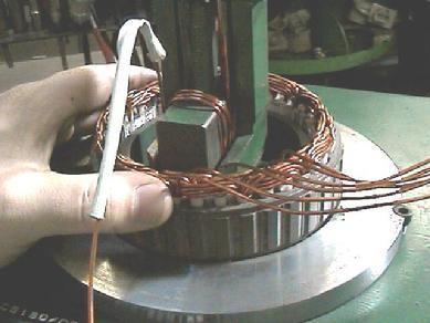
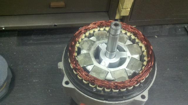
Elements of the VAZ-2107 generator
Like any electric motor, a generator has two main elements - a stator and a rotor with windings, which are named accordingly. Alternating current generators are widely used in automotive technology. Moreover, the output voltage is three-phase. This has its own advantages, such as reducing the ripple of the generated current. With the help of a diode bridge rectifier, three-phase alternating voltage is converted into direct voltage. After this comes an electrolytic capacitor, which cuts off all variable components. These are all components that relate to the electrical part of the VAZ-2107. Replacing a generator or repairing it requires familiarization with all the details.
At the output of the generator, which is connected to the battery, appears constant pressure when the rotor rotates (with the engine running). But this doesn't always happen. In order for voltage to appear at the output of the generator, it is necessary to power the rotor excitation winding; by the way, the battery receives not 12 volts, but more. Sometimes the voltage jumps to 30 V. And how to fix this? There's a little trick here. There is no need to stabilize the high current at the output; it is enough to supply a stabilized voltage to the excitation winding. The magnetic field around the rotor becomes constant, there is no pulsation, therefore, the output of the car generator will have a stabilized voltage.
What is a voltage regulator for and how does it work?
The function of a stabilizer is performed by a voltage regulator. It can be either mechanical or electronic. True, the latter have long conquered the market, displacing their predecessor. This is understandable, because the reliability of an electronic regulator is many times higher. The reason is that there are no contacts or moving elements. The latest regulators are housed in one block with brushes, which makes the device more compact.

The battery supplies voltage to the relay regulator. There is an incandescent lamp in the power circuit, which indicates the presence or absence of battery charging. It is located on the dashboard and looks like a red battery. If this lamp suddenly starts to light up, it means that the generator is not working. The reason could be any: the belt of the VAZ-2107 generator broke, or there was a wiring problem, or maybe the windings failed. This indicates that corrective action needs to be taken.
How to remove the generator?
The generator should be removed only after the battery has been disconnected. Remember that there is a thick power wire going to the back cover; it is not protected by any fuses, so the risk of a fire or short circuit is very high. Do not forget that although the VAZ-2107 generator has a simple mechanism, its price is quite high: domestic models will cost you 3500 rubles, and imported ones - about 4200-4400. Therefore, it turns out to be cheaper to carry out major repairs.
First you need to remove the belt. Unscrew the nut at the top of the generator, and then move it towards the engine with your hands. Remove the belt, this is the only part that was in your way. Inspect it carefully for cracks and cuts. If you find them, you will have to install a new one. There is a long bolt at the bottom of the generator. Unscrew the nut from it, and then remove it from the holes in the generator and engine block. Before doing this, it is best to unscrew all the wires attached to the back cover so as not to damage them.
How to check windings and diodes?
First you need to disassemble the VAZ-2107 generator. How to check its elements? The first step is to carry out a visual inspection. Take a look at the windings: are there any dents or other damage on them, are they burnt? The brushes must be of sufficient length; if they are worn out, replace them. Try to rotate the inner races of the bearings, pay attention to whether there is any play in them.
But there are also faults that cannot be diagnosed visually or by touch. For example, the integrity of diodes cannot be checked without a tester or lamp. Everyone knows from physics that a diode is a semiconductor. In other words, he conducts D.C. only in one direction. Take a tester and test each diode, and you need to change the polarity. Then connect the tester to the ends of the windings and check the resistance of each. If it is not there, then there is a break inside, and if there is, then it should be the same as indicated in the generator passport. A short circuit to the housing can be detected by connecting the tester to it and to the winding terminal.
Generator installation
When the diagnostics have been carried out and all faults have been eliminated, assemble the generator. Then you can begin installing it on the car. There is nothing complicated about this; it is performed in the reverse order of removal. But you should pay attention to the belt. It must be installed correctly, with the required tension. Please note that weak tension will cause bad charging battery Do not forget that when connecting consumers with high power, the generator simply starts to slow down and is very difficult to turn over. And if you tighten the belt too much, then in the near future the bearing on the front cover will fail and begin to make a nasty whistle.

Afterword
Do not neglect the generator, monitor it, take care of it, keep it clean and in good condition. technical condition. Do not forget that the VAZ-2107 generator, the price of which even at disassembly is 2000-2500 rubles, does not often require replacement. The reason for this can only be the complete destruction of the mounting eyes or a severe blow to the generator. In most cases, repairs turn out to be much cheaper and more accessible.
Maximum output current at 14 V and rotor speed 5000 min-1, A........ 55 (45*)
Limits of regulated voltage, V........ 14.1±0.5
Maximum rotor speed, min-1........ 13000
Engine-generator gear ratio........ 1: 2.04
* For generator G-222.
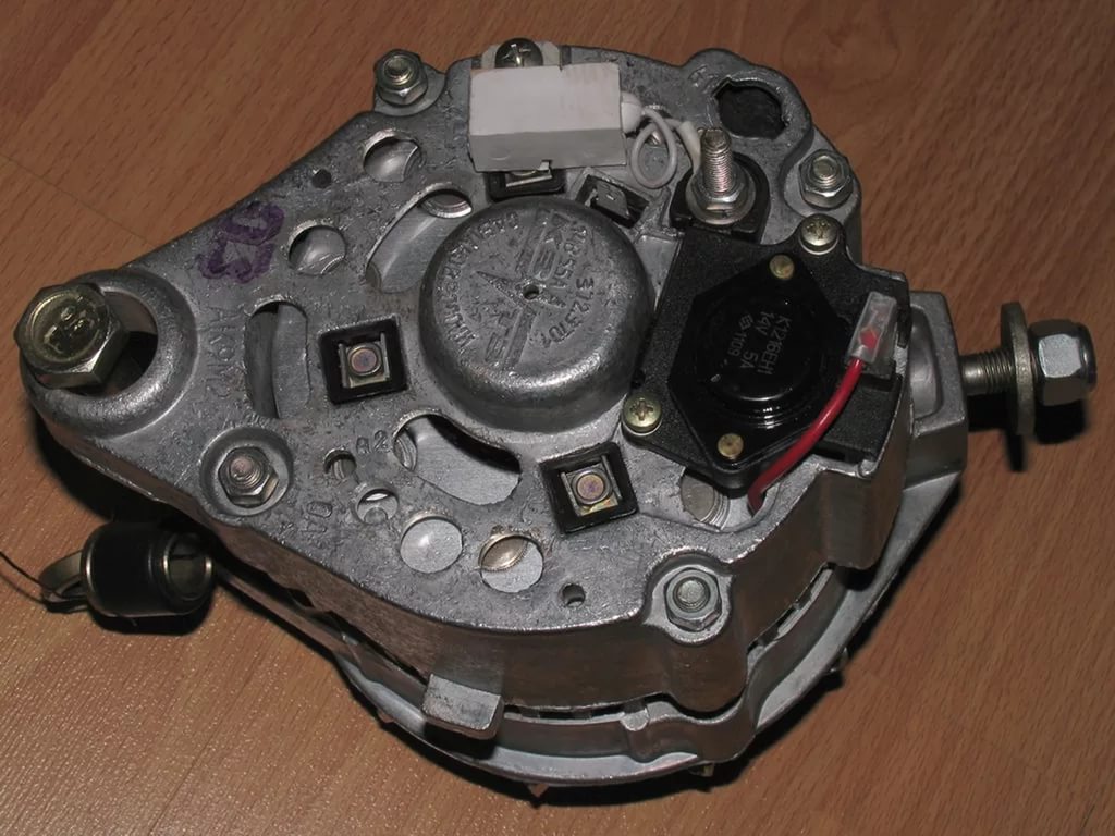
Generator 37.3701: a - voltage regulator and brush assembly for generators produced since 1996; 1 - generator cover from the slip ring side; 2 - bolt for fastening the rectifier unit; 3 - slip rings; 4 – ball bearing of the rotor shaft on the slip ring side; 5 - capacitor 2.2 µF ±20% to suppress radio interference; 6 - rotor shaft; 7 - common output wire for additional diodes; 8 - terminal “30” of the generator for connecting consumers; 9 - plug “61” of the generator (common output of additional diodes); 10 - output wire “B” of the voltage regulator; 11 - brush connected to terminal “B” of the voltage regulator; 12 - voltage regulator; 13 - brush connected to terminal "Ш" of the voltage regulator; 14 - pin for attaching the generator to tensioner; 15 - generator cover from the slip ring side; 16 - fan impeller with generator drive pulley; 17 - rotor pole piece; 18 - bearing mounting washers; 19 - spacer ring; 20 - ball bearing of the rotor shaft on the drive side; 21 - steel bushing; 22 - rotor winding (excitation winding); 23 - stator core; 24 - stator winding; 25 - rectifier block; 26 - generator coupling bolt; 27 - buffer sleeve; 28 - bushing; 29 - clamping sleeve; 30 - terminal "B" of the voltage regulator; 31 - brush holder
Since 1988, VAZ-2107 cars have used a three-phase alternating current generator VAZ 2104, VAZ 2105, VAZ 2107 type 37.3701 with a built-in rectifier unit and a microelectronic voltage regulator. Small batches of VAZ-2107 cars can be equipped with generators made in Bulgaria, Slovenia or Germany. These VAZ 2104 generators are interchangeable with the VAZ 2107 37.3701 generator in terms of characteristics and installation dimensions, but are slightly different in design.
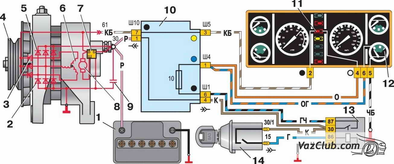
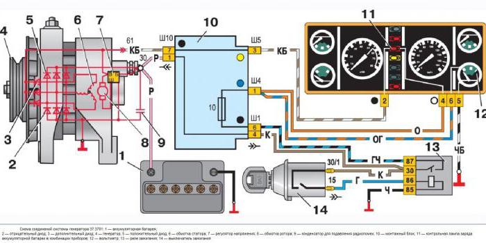
Connection diagram of the generator system 37.3701: 1 - battery;
2 - negative diode; 3 - additional diode; 4 - generator; 5 - positive diode; 6 - stator winding; 7 - voltage regulator; 8 - rotor winding; 9 - capacitor for suppressing radio interference; 10 - mounting block; 11 - battery charge indicator lamp in the instrument cluster; 12 - voltmeter; 13 - ignition relay; 14 - ignition switch

Connection diagram of the G-222 generator system: 1 - generator; 2 - negative diode; 3 - positive diode; 4 - stator winding; 5 – voltage regulator; 6 – rotor winding; 7 – capacitor for suppressing radio interference; 8 - battery; 9 - battery charge warning lamp relay; 10 - mounting block; 11 - battery charge indicator lamp in the instrument cluster; 12 - voltmeter; 13 - ignition relay; 14 - ignition switch
Generator connection diagram 37.3701. The voltage to excite the VAZ 2107 generator when the ignition is turned on is supplied to terminal “B” of the regulator through test lamp 11. After the engine starts, the excitation winding is powered by three additional diodes 3 installed on the rectifier unit. In this case, no current passes through the control lamp, and it does not light up. The control voltage is supplied to terminal “B” of the regulator directly from terminal “30” of the generator. The "Ш" pin of the regulator is not marked. Brush 13 is connected to it. The voltage in the vehicle’s on-board network is controlled by voltmeter 12.
Since 1996, the design of the voltage regulator and brush holder for the VAZ 2105 generator 37.3701 has been changed. Now the voltage regulator is placed in a metal case and riveted to the brush holder, i.e. forms an inseparable knot with it. The new voltage regulator does not have terminal “B” and voltage is supplied only to terminal “B”. In terms of their characteristics, the old and new voltage regulators are the same and, when assembled with a brush holder, are interchangeable.
WARNINGS
The "minus" of the battery should always be connected to ground, and the "plus" should always be connected to terminal "30" of the generator. Incorrectly turning the battery back on will immediately cause an increased current through the diodes of the rectifier block of the Lada Classic generator, and they will be damaged.
It is not allowed to operate the generator with the battery disconnected. This causes high voltage pulses to appear at terminal “30” of the generator, which can damage the generator voltage regulator and electronic devices in the vehicle’s on-board network.
It is prohibited to check the functionality of the generator “for spark” even by briefly connecting terminal “30” of the generator to ground. In this case, significant current flows through the diodes and they are damaged. The generator can only be checked using an ammeter and voltmeter.
The diodes of the generator rectifier unit must not be checked with a voltage of more than 12 V or with a megger, since it has a voltage too high for the diodes and they will be broken during testing (a short circuit will occur).
WARNINGS
It is prohibited to check the electrical wiring of a VAZ 2104 car with a megger or a lamp powered by a voltage of more than 12 V. If such a check is necessary, you must first disconnect the wires from the generator.
The insulation resistance of the stator winding with increased voltage should only be checked on a bench and always with the phase winding terminals disconnected from the rectifier unit.
When electric welding components and body parts of a VAZ 2104, VAZ 2105, VAZ 2107 car, the wires should be disconnected from all terminals of the generator and battery.
Until 1988, the G-222 generator was used. It differed from the 37.3701 generator in the data of the rotor and stator windings of the VAZ 2105, the voltage regulator and brush assembly, as well as the design of the rectifier unit. Connection diagram for generator G-222. At the beginning of the production of VAZ-2107 cars, relay 9 of warning lamp 11 was installed. In 1985, it was canceled, and the wires connected to the relay and warning lamp were removed from the wiring harnesses. The voltage generated by the generator was controlled only by a voltmeter 12.
Generator VAZ 2107, VAZ 2105, VAZ 2104
- - Technical characteristics of the generator
- - Generator troubleshooting
- - Checking the generator on the stand
- - Checking the generator with an oscilloscope
- - Generator rotor winding
- - Generator stator
Technical specifications generator VAZ 2107, VAZ 2105, VAZ 2104
Malfunctions of the VAZ 2107, VAZ 2105, VAZ 2104 generator, their causes and methods of elimination
Checking the generator VAZ 2107, VAZ 2105, VAZ 2104 at the stand
Checking the generator VAZ 2107, VAZ 2105, VAZ 2104
Checking the rotor winding of the generator VAZ 2107, VAZ 2105, VAZ 2104
Checking the stator of the generator VAZ 2107, VAZ 2105, VAZ 2104
The generator in a car is one of the most important components, which ensures stable operation of the on-board electrical network after starting the internal combustion engine. The device's responsibilities also include charging the battery. Thus, if the device fails, the battery will quickly run out due to lack of charging. Diagnostics can be carried out without even removing the unit.
During the troubleshooting process, the following elements are checked:
- Belt.
- Diodes.
- Capacitors.
- Voltage regulator.
- Rotor winding.
- After the internal combustion engine has been started, the output voltage does not correspond to normal values and after some time stabilizes when the devices that consume electricity are turned off.
- After starting up energy-consuming appliances, the readings drop again.
Based on this situation, the problem lies in the belt, which is slipping due to weakening or natural wear. It is best to replace the used element; there is no point in re-tensioning it. Check the condition of the pulley. Is the belt sitting too deep? Then this part needs to be changed.
Diode diagnostics
You will need a multimeter to check. Set the meter to ohmmeter mode and connect the positive probe to terminal 30, and the negative probe to the generator housing. If the indicators are close to zero, this means that there is a breakdown of the diodes. Otherwise, there may be a short circuit in the stator winding.
Positive diodes are checked by connecting the positive probe to the 30th pin, and the negative one to the bolt that secures the generator rectifier. Negative diodes can be checked by connecting the positive contact to the block mounting bolt, and the negative contact to the generator housing.
Capacitors are diagnosed only after they are removed from the power generation device.
When connecting elements to an ohmmeter, the readings first decrease and then increase (resistance).
Checking the condition of the voltage regulator
Remove the regulator from the generator. Before doing this, inspect the condition of the brushes. If they move freely in the grooves and spring back, then everything is fine. Otherwise, they can become the root cause for replacing the generator when the brushes in a free position extend 5 mm or more from the brush holder.
Diagnostics without dismantling
To troubleshoot, you will need a multimeter and a test light. By measuring voltages, you can determine a potential breakdown that needs to be eliminated.
Initially, determine the voltage value while the engine is running at medium speeds with the load on (high beam, for example). Indicators in the range of 14.5-13.5 V indicate that everything is normal. Otherwise, repeat the test with electrical appliances turned off. Additionally, find out what voltage is supplied between pin 30 and the generator housing.
If, during the diagnostic process, the voltage at the battery terminals with the load on is below 13.5 V, and with the consumers turned off, the indicators slowly rise to 13-13.4. Then the problem most likely lies in poor contact from pin 30 to the battery and poor contact of the negative terminal to the motor housing.
To check the reliability of the connection in the 30th terminal of the unit, measure the voltage between the contact and the generator housing. If the indicator is significantly higher than the number on the battery terminals then do the following:
- Unscrew the nut securing the wire.
- Clean the connections.
- Pull the terminal nut that is located between the wire and the generator.
 If you leave everything as is, a poor connection will cause the contact bolt to become very hot.
If the measurements show a value greater than 13.5 V, then do the following:
- Take a measurement between the positive side of the generator and its housing.
- If the value is the same as between the 30th pin and the housing, then eliminate the contact between the negative terminal of the generator and the motor housing.
- If the value is lower, check the voltage readings in contact connections circuits from the generator to the battery.
- The same results at the battery terminals and pin 30 indicate that the generator itself is faulty. In this case, the rectifier bridge diode most often fails.
Depending on the year of manufacture of the car, the connection diagram for the VAZ-2107 generator may vary. Over the years, various devices have been added to the car, and electricity consumption has increased. If in the early 80s you could find a radio or (in very rare cases) a cassette recorder on cars, today the list is supplemented by central locks, alarm and security systems, and acoustics (subwoofers, powerful amplifiers).
Various types of devices help the driver - DVRs, navigators, inverters, charging device, pumps, etc. And they all consume electricity, and the generator helps replenish the charge, which charges the battery to the optimal level.
Carburetor engines
The connection diagram for the VAZ-2107 generator (carburetor and injector) depends on the year of manufacture of the car. The first carburetor models had a G-222 generator installed. The same device can be found on commercially produced VAZ-2105 and VAZ-2104 models with a carburetor injection system.
The maximum output current for such an installation is 55 amperes. But in last years Cars with fuel injection systems have become widespread. Its use implies a large current consumption, so it is necessary to use a generator with a high current to ensure a normal charge level and power supply to all consumers.
Injection engines

On injection engines, generator sets 5142.3771 or similar are used. They have increased energy, the maximum current is about 80-90 A, it all depends on the design option. Cars of the seventh series and similar models are good because they are like a designer set. You can install almost any generator on them, similar in design to the “native” one.
For tuning, installations with an output current of 100 amperes and higher are used. But the use of such devices is justified only if many powerful consumers are connected to the electrical equipment. Regardless of the design, the generators produce alternating current; a voltage regulator, capacitor and diode block are installed in the housing.
Cars before 1986
The G-222 generator was used in cars. The connection diagram for the VAZ-2107 is almost the same as on later models. But there are features, among the main ones - there is a control lamp indicating battery charging. Moreover, it worked using an electromagnetic relay.
When the ignition is turned on, power is supplied from the lock through the instrument panel fuse to the electromagnetic relay of the battery charge lamp and the coil contact. The second contact of the coil is connected to the center wire on the generator (the point where the three windings connect).
The electromagnetic relay has normally closed contacts, so when the ignition is turned on, the lamp lights up. But as soon as the engine starts running, the generator produces current. And a current flows through the control lamp coil, which causes the armature to attract and open the contacts.
At the same time, the power to the incandescent lamp stops and it goes out. This indicates that the battery is charging normally. Only when the power supply to the lamp stops will voltage be applied to the excitation winding and the generator will be able to return to operating mode.
Cars manufactured in 1996 and later (carburetor engines)
The connection diagram for the G222 generator on a VAZ-2107 after 1996 differs from the previous one in one small feature - the power supply to the excitation winding has been changed. Cars have been improved, and some improvements make it possible to kill two birds with one stone - simplify the design and make the fate of the driver easier.
After 1996, instead of a warning lamp, they began to install a voltmeter, which more or less accurately shows the battery charge level. And if the lamp allows you to monitor only the presence or absence of voltage on the generator, then using a voltmeter the driver visually assesses the level. And if necessary, it can understand that repairs or maintenance are necessary.
Generator circuit for injection engines

In fact, the design of the generator set is not much different from those installed on carburetor engines. Only the type of excitation and serviceability monitoring differ. The dashboard contains not only a warning lamp, but also a voltmeter; these two devices allow you to assess both the presence and level of charging. Current flows through the lamp filament and is supplied to the field winding when the engine starts. The connection diagram for the VAZ-2107 generator, regardless of the year of manufacture, implies operation in the following mode:
- When the ignition is turned on, power is supplied to the excitation winding. A magnetic field appears around the armature.
- When the crankshaft rotates with the starter, the generator armature also begins to move. With movement and magnetic field A potential difference occurs at the ends of the stator windings.
- From the windings, voltage (alternating, three-phase) is supplied to the rectifier unit, and from it to terminal “30” of the generator.
- Pin “30” is connected to the battery (positive terminal). Consequently, the entire electrical system is powered and the battery is charged.
In this case, the battery and generator G221A work in parallel. The connection diagram for the VAZ-2107 with carburetor and injection engines is almost identical, with only minor features.
Conclusion

If a control lamp is provided, then current will flow through it, regardless of whether the generator or battery powers the power supply system, they work in pairs. But if there is a break in the excitation winding, the brushes are worn out, then the lamp will not go out, since the generator will not be able to reach normal operating mode and provide power to all consumers. The connection diagram for the VAZ-2107 generator does not have any other features.
An almost similar one is used on all cars (and not only those produced by AvtoVAZ, but also from other factories). The power supply circuit for the excitation winding is standard; the laws of electrodynamics are the same everywhere. Without power to the rotor winding, it will not be possible to remove voltage from the stator terminals, since there will be no rotating magnetic field.