Make your own CNC milling machine. Step-by-step instructions for assembling a CNC machine with your own hands
And so, as part of this instructional article, I want you, together with the author of the project, a 21-year-old mechanic and designer, to make your own. The narration will be conducted in the first person, but know that, to my great regret, I am not sharing my experience, but only freely retelling the author of this project.
There will be quite a lot of drawings in this article., notes to them are made on English language, but I’m sure that a real techie will understand everything without further ado. For ease of understanding, I will break the story into “steps”.
Preface from the author
Already at the age of 12, I dreamed of building a machine that would be capable of creating various things. A machine that will give me the ability to make any household item. Two years later I came across the phrase CNC or to be more precise, the phrase "CNC milling machine". After I found out that there are people who can make such a machine on their own for their own needs, in their own garage, I realized that I could do it too. I must do it! For three months I tried to collect suitable parts, but did not budge. So my obsession gradually faded.
In August 2013, the idea of building a CNC milling machine captured me again. I had just graduated from a bachelor's degree in industrial design at university, so I was quite confident in my abilities. Now I clearly understood the difference between me today and me five years ago. I learned how to work with metal, mastered techniques for working with manual metalworking machines, but most importantly, I learned how to use development tools. I hope this tutorial inspires you to build your own CNC machine!
Step 1: Design and CAD model
It all starts with thoughtful design. I made several sketches to get a better feel for the size and shape of the future machine. After that I created a CAD model using SolidWorks. After I modeled all the parts and components of the machine, I prepared technical drawings. I used these drawings to make parts on manual metalworking machines: and.
I confess honestly, I love good convenient tools. That is why I tried to make sure that the operations maintenance and adjustment of the machine were carried out as simply as possible. I placed the bearings in special blocks in order to be able to quickly replace them. The guides are accessible for maintenance, so my car will always be clean when the work is completed.


Files for downloading “Step 1”
dimensions
Step 2: Bed
The bed provides the machine with the necessary rigidity. A movable portal, stepper motors, a Z axis and a spindle, and later a working surface will be installed on it. To create the supporting frame I used two aluminum profiles Maytec with a cross section of 40x80 mm and two end plates made of aluminum 10 mm thick. I connected all the elements together using aluminum corners. To strengthen the structure inside the main frame, I made an additional square frame from profiles of a smaller section.
In order to avoid dust getting on the guides in the future, I installed protective aluminum corners. The angle is mounted using T-nuts, which are installed in one of the profile grooves.
Both end plates have bearing blocks for mounting the drive screw.


Support frame assembly


Corners for protecting guides
Files for downloading “Step 2”
Drawings of the main elements of the frame
Step 3: Portal
The movable portal is the executive element of your machine; it moves along the X axis and carries the milling spindle and Z axis support. The higher the portal, the thicker the workpiece that you can process. However, a high portal is less resistant to the loads that arise during processing. The high side posts of the portal act as levers relative to the linear rolling bearings.
The main task that I planned to solve on my CNC milling machine was the processing of aluminum parts. Since the maximum thickness of the aluminum blanks that suit me is 60 mm, I decided to make the portal clearance (the distance from the working surface to the upper cross beam) equal to 125 mm. I converted all my measurements into a model and technical drawings in SolidWorks. Due to the complexity of the parts, I processed them on an industrial CNC machining center; this additionally allowed me to process chamfers, which would be very difficult to do on a manual metal milling machine.


Files for downloading “Step 3”
Step 4: Z Axis Caliper
For the Z axis design, I used a front panel that attaches to the Y axis motion bearings, two plates to reinforce the assembly, a plate to mount the stepper motor, and a panel to mount the milling spindle. On the front panel I installed two profile guides along which the spindle will move along the Z axis. Please note that the Z axis screw does not have a counter support at the bottom.


Downloads “Step 4”
Step 5: Guides
Guides provide the ability to move in all directions, ensuring smooth and precise movements. Any play in one direction can cause inaccuracy in the processing of your products. I chose the most expensive option - profiled hardened steel rails. This will allow the structure to withstand high loads and provide the positioning accuracy I need. To ensure the guides were parallel, I used a special indicator while installing them. The maximum deviation relative to each other was no more than 0.01 mm.


Step 6: Screws and Pulleys
Screws convert rotary motion from stepper motors into linear motion. When designing your machine, you can choose several options for this unit: a screw-nut pair or a ball screw pair (ball screw). The screw-nut, as a rule, is subjected to more frictional forces during operation, and is also less accurate relative to the ball screw. If you need increased accuracy, then you definitely need to opt for a ball screw. But you should know that ball screws are quite expensive.
The goal of this project is to create a desktop CNC machine. It was possible to buy a ready-made machine, but its price and dimensions did not suit me, and I decided to build a CNC machine with the following requirements:
- usage simple tools(you only need a drilling machine, band-saw and hand tools)
- low cost (I was focusing on low cost, but still bought elements for about $600, you can save a lot by buying elements in relevant stores)
- small footprint (30"x25")
- normal working space (10" along the X axis, 14" along the Y axis, 4" along the Z axis)
- high cutting speed (60" per minute)
- small number of elements (less than 30 unique)
- available elements (all elements can be purchased in one hardware store and three online stores)
- possibility of successful processing of plywood
Other people's machines
Here are a few photos of other machines collected from this article

Photo 1 – Chris and a friend assembled the machine, cutting out parts from 0.5" acrylic using laser cutting. But everyone who has worked with acrylic knows that laser cutting this is good, but acrylic doesn't hold up well to drilling and there are a lot of holes in this project. They did Good work, more information can be found on Chris's blog. I especially enjoyed making a 3D object using 2D cuts.

Photo 2 - Sam McCaskill did a really good one table machine with CNC. I was impressed that he did not simplify his work and cut all the elements by hand. I'm impressed with this project.

Photo 3 - Angry Monk's used laser-cut DMF parts and toothed-belt motors converted into propeller motors.

Photo 4 - Bret Golab's assembled the machine and configured it to work with Linux CNC (I also tried to do this, but could not due to the complexity). If you are interested in his settings, you can contact him. He did a great job!
I'm afraid I don't have enough experience and knowledge to explain the basics of CNC, but the CNCZone.com forum has an extensive section dedicated to homemade machines, which has helped me a lot.

Cutter: Dremel or Dremel Type Tool
Axes parameters:
X axis
Travel Distance: 14"
Speed: 60"/min
Acceleration: 1"/s2
Resolution: 1/2000"
Pulses per inch: 2001
Y axis
Travel Distance: 10"
Drive: Toothed belt drive
Speed: 60"/min
Acceleration: 1"/s2
Resolution: 1/2000"
Pulses per inch: 2001
Z axis (up-down)
Travel Distance: 4"
Drive: Screw
Acceleration: .2"/s2
Speed: 12"/min
Resolution: 1/8000"
Pulses per inch: 8000
Required Tools
I aimed to use popular tools that can be purchased at a regular DIY store.

Power tools:
- band saw or jigsaw
- drilling machine (drills 1/4", 5/16", 7/16", 5/8", 7/8", 8mm (about 5/16"), also called Q
- Printer
- Dremel or similar tool (for installation into a finished machine).
Hand tool:
- rubber hammer (for putting elements in place)
- hexagons (5/64", 1/16")
- screwdriver
- glue stick or spray glue
- adjustable wrench (or socket wrench with ratchet and 7/16" socket
Necessary materials
The attached PDF file (CNC-Part-Summary.pdf) provides all costs and information about each item. Only generalized information is provided here.

Sheets --- $20
-Piece 48"x48" 1/2" MDF (any sheet material 1/2" thick I plan to use UHMW in the next version of the machine, but now it is too expensive)
-Piece of 5"x5" 3/4" MDF (this piece is used as a spacer, so you can take a piece of any 3/4" material
Motors and Controllers --- $255
-You could write a whole article about the choice of controllers and motors. In short, you need a controller capable of driving three motors and motors with torque of around 100 oz/in. I bought the motors and a ready-made controller and everything worked well.
Hardware --- $275
-I bought these items in three stores. I bought simple elements at a hardware store, I bought specialized drivers at McMaster Carr (http://www.mcmaster.com), and I bought bearings, which I need a lot of, from an online seller, paying $40 for 100 pieces (it turns out to be quite profitable , many bearings remain for other projects).
Software ---(Free)
-You need a program to draw your design (I use CorelDraw) and I'm currently using a trial version of Mach3, but I have plans to move to LinuxCNC (an open source machine controller using Linux)
Head unit --- (optional)
-I installed Dremel on my machine, but if you are interested in 3D printing (eg RepRap) you can install your own device.
Printing templates
I had some experience with a jigsaw, so I decided to glue down the templates. Need to print PDF files with the templates placed on the sheet, glue the sheet onto the material and cut out the parts.

File name and material:
All: CNC-Cut-Summary.pdf
0.5" MDF (35 8.5"x11" template sheets): CNC-0.5MDF-CutLayout-(Rev3).pdf
0.75" MDF: CNC-0.75MDF-CutLayout-(Rev2).pdf
0,75" aluminum tube: CNC-0.75Alum-CutLayout-(Rev3).pdf
0.5" MDF (1 48"x48" Pattern Sheet): CNC-(One 48x48 Page) 05-MDF-CutPattern.pdf
Note: I am attaching the CorelDraw drawings in the original format (CNC-CorelDrawFormat-CutPatterns (Rev2) ZIP) for those who would like to change something.
Note: There are two file options for MDF 0.5". You can download a file with 35 pages 8.5"x11" (CNC-0.5MDF-CutLayout-(Rev3), PDF), or a file (CNC-(One 48x48 Page) 05- MDF-CutPattern.pdf) with one sheet of 48"x48" for printing on a wide format printer.
Step by step:
1. Download three PDF template files.
2. Open each file in Adobe Reader
3. Open the print window
4. (IMPORTANT) disable Page Scaling.
5. Check that the file has not been accidentally scaled. The first time I didn't do this, I printed everything at 90% scale, as described below.
Gluing and cutting out elements
Glue the printed templates onto the MDF and onto the aluminum pipe. Next, simply cut out the part along the contour.


As mentioned above, I accidentally printed the templates at 90% scale and didn't notice until I started cutting. Unfortunately, I didn't realize this until this stage. I was left with 90% scale templates and after moving across the country I had access to a full size CNC machine. I couldn't resist and cut out the elements using this machine, but I couldn't drill them with reverse side. That is why all the elements in the photographs are without pieces of the template.

Drilling
I didn't count exactly how many, but this project uses a lot of holes. The holes that are drilled at the ends are especially important, but take your time on them and you will rarely need to use a rubber hammer.
Places with holes in the overlay on top of each other are an attempt to make grooves. Perhaps you have a CNC machine that can do this better.
If you have made it this far, then congratulations! Looking at a bunch of elements, it is quite difficult to imagine how to assemble the machine, so I tried to make detailed instructions, similar to the instructions for LEGO. (Attached PDF CNC-Assembly-Instructions.pdf). They look quite interesting step by step photos assemblies.


Ready!
The machine is ready! I hope you got it up and running. I hope that the article does not miss important details and points. Here's a video showing the machine cutting out a pattern on pink foam board.

So, you've decided to build a homemade CNC milling machine, or maybe you're just thinking about it and don't know where to start? There are many benefits to having a CNC machine. Home machines can mill and cut almost all materials. Whether you are an amateur or a craftsman, this opens up great horizons for creativity. The fact that one of the machines could end up in your workshop is even more tempting.
There are many reasons why people want to build their own DIY CNC router. As a rule, this happens because we simply cannot afford to buy it in a store or from a manufacturer, and this is not surprising, because the price for them is rather high. Or you can be like me and have a lot of fun with your own work and creating something unique. You can simply do this to gain experience in mechanical engineering.
Personal experience
When I first started developing, thinking through and making the first CNC router with my own hands, it took about one day to create the project. Then, when I started buying parts, I did some research. And I found some information in various sources and forums, which led to new questions:
- Do I really need ball screws, or will regular studs and nuts work just fine?
- Which linear bearing is best and can I afford it?
- What motor parameters do I need, and is it better to use a stepper or a servo drive?
- Does the housing material deform too much when large size machine?
- And so on.
Fortunately, I was able to answer some of the questions thanks to my engineering and technical background left after my studies. However, many of the problems I would encounter could not be calculated. I just needed someone with practical experience and information on this issue.
Of course, I received many answers to my questions from different people, many of which contradicted each other. Then I had to do more research to figure out which answers were worthwhile and which were garbage.
Every time I had a question that I didn't know the answer to, I had to repeat the same process. By and large, this is due to the fact that I had a limited budget and wanted to take the best that my money could buy. This is the same situation for many people who create a homemade CNC milling machine.

Kits and kits for assembling CNC routers with your own hands
Yes, there are machine kits available for hand assembled, but I have yet to see one that can be tailored to specific needs.
There is also no possibility to make changes to the design and type of machine, but there are many of them, and how do you know which one is right for you? No matter how good the instructions are, if the design is poorly thought out, then the final machine will be poor.
That's why you need to be aware of what you're building and understand the role each piece plays!

Management
This guide aims to prevent you from making the same mistakes that I wasted my precious time and money on.
We'll look at all the components down to the bolts, looking at the advantages and disadvantages of each type of each part. I will talk about every aspect of design and show you how to create a CNC milling machine with your own hands. I'll take you through the mechanics to the software and everything in between.
Keep in mind that homemade CNC machine plans offer few solutions to some problems. This often results in sloppy design or poor machine performance. That's why I suggest you read this guide first.

LET'S START
STEP 1: Key design decisions
First of all, the following questions need to be considered:
- Definition suitable design specifically for you (for example, if you make a woodworking machine with your own hands).
- Required processing area.
- Availability of work space.
- Materials.
- Tolerances.
- Design methods.
- Available tools.
- Budget.

STEP 2: Base and X-Axis
The following questions are addressed here:
- Design and build the main base or X-axis base.
- Rigidly fixed parts.
- Partially fixed parts, etc.

STEP 3: Design the Gantry Y Axis
- Design and construction of the portal Y axis.
- Breakdown of various structures into elements.
- Forces and moments on the portal, etc.

STEP 4: Z Axis Assembly Diagram
The following questions are addressed here:
- Design and assembly of Z axis assembly.
- Forces and moments on the Z axis.
- Linear rails/guides and bearing spacing.
- Selecting a cable channel.

STEP 5: Linear Motion System
This paragraph addresses the following issues:
- A detailed study of linear motion systems.
- Choice correct system specifically for your machine.
- Design and construction of your own guides on a low budget.
- Linear shaft and bushings or rails and blocks?

STEP 6: Mechanical Drive Components
This paragraph covers the following aspects:
- Detailed overview of drive parts.
- Selecting the right components for your machine type.
- Stepper or servo motors.
- Screws and ball screws.
- Drive nuts.
- Radial and thrust bearings.
- Engine coupling and mount.
- Direct drive or gearbox.
- Racks and gears.
- Calibration of propellers relative to engines.

STEP 7: Selecting Motors
In this step you need to consider:
- Detailed review of CNC motors.
- Types of CNC motors.
- How stepper motors work.
- Types of stepper motors.
- How do servomotors work?
- Types of servo motors.
- NEMA standards.
- Choosing the right motor type for your project.
- Measuring motor parameters.

STEP 8: Cutting table design
- Design and build your own tables on a low budget.
- Perforated cutting layer.
- Vacuum table.
- Review of cutting table designs.
- The table can be cut using a CNC wood router.

STEP 9: Spindle Parameters
This step addresses the following issues:
- Review of CNC spindles.
- Types and functions.
- Pricing and costs.
- Mounting and cooling options.
- Cooling systems.
- Creating your own spindle.
- Calculation of chip load and cutting force.
- Finding the optimal feed rate.

STEP 10: Electronics
This paragraph addresses the following issues:
- Control Panel.
- Electrical wiring and fuses.
- Buttons and switches.
- MPG and Jog circles.
- Power supplies.

STEP 11: Program Controller Parameters
This step addresses the following issues:
- Overview of the CNC controller.
- Controller selection.
- Available options.
- Closed-loop and open-loop systems.
- Controllers at an affordable price.
- Creating your own controller from scratch.

STEP 12: Select Software
This paragraph addresses the following issues:
- Review of CNC related software.
- Selection of software.
- CAM software.
- CAD software.
- NC Controller software.
——————————————————————————————————————————————————–
The article describes a homemade CNC machine. Main advantage this option machine tool - a simple method of connecting stepper motors to a computer via the LPT port.
Mechanical part
Bed The bed of our machine is made of plastic with a thickness of 11-12mm. The material is not critical, you can use aluminum, organic glass, plywood and any other available material. The main parts of the frame are attached using self-tapping screws; if desired, you can additionally decorate the fastening points with glue; if you use wood, you can use PVA glue.
Calipers and guides Steel rods with a diameter of 12 mm, length 200 mm (Z axis 90 mm), two pieces per axis, were used as guides. The calipers are made of textolite with dimensions 25X100X45. Textolite has three through holes, two of them for the guides and one for the nut. The guide parts are fastened with M6 screws. The X and Y supports at the top have 4 threaded holes for attaching the table and Z axis assembly.

Caliper Z The guides of the Z axis are attached to the caliper X through a steel plate, which is a transition plate, dimensions of the plate are 45x100x4.


Stepper motors are mounted on fasteners, which can be made of sheet steel with a thickness of 2-3mm. The screw must be connected to the axis of the stepper motor using a flexible shaft, which can be a rubber hose. If you use a rigid shaft, the system will not work accurately. The nut is made of brass, which is glued into the caliper.

Assembly Assembly of a homemade CNC machine is carried out in the following sequence:
- First you need to install all the guide components in the calipers and screw them to the sidewalls, which are not first installed on the base.
- We move the caliper along the guides until we achieve smooth movement.
- Tighten the bolts, fixing the guide parts.
- We attach the caliper, guide assembly and side frame to the base; we use self-tapping screws for fastening.
- We assemble assembly Z and, together with the adapter plate, attach it to support X.
- Next, install the lead screws along with the couplings.
- We install stepper motors by connecting the motor rotor and the screw with a coupling. We pay strict attention to ensure that the lead screws rotate smoothly.
Recommendations for assembling the machine: Nuts can also be made from cast iron; you should not use other materials; screws can be bought at any hardware store and cut to suit your needs. When using screws with M6x1 thread, the nut length will be 10 mm.
Machine drawings.rar
Let's move on to the second part of assembling a CNC machine with our own hands, namely the electronics.
Electronics
Power supply A 12V 3A unit was used as a power source. The block is designed to power stepper motors. Another voltage source of 5 Volts and a current of 0.3 A was used to power the controller microcircuits. The power supply depends on the power of the stepper motors.
Here is the calculation of the power supply. The calculation is simple - 3x2x1=6A, where 3 is the number of stepper motors used, 2 is the number of powered windings, 1 is the current in Amperes.

Control controller The control controller was assembled using only 3 555TM7 series microcircuits. The controller does not require firmware and has a fairly simple circuit diagram, thanks to this, this CNC machine can be made by a person who is not particularly versed in electronics.

Description and purpose of the LPT port connector pins.
| Vvyv. | Name | Direction | Description |
| 1 | STROBE | input and output | Sets the PC after each data transfer is completed |
| 2..9 | DO-D7 | conclusion | Conclusion |
| 10 | ASK | input | Set to "0" external device after receiving the byte |
| 11 | BUSY | input | The device indicates that it is busy by setting this line to "1" |
| 12 | Paper out | input | For printers |
| 13 | Select | input | The device indicates that it is ready by setting this line to "1" |
| 14 | Autofeed | ||
| 15 | Error | input | Indicates an error |
| 16 | Initialize | input and output | |
| 17 | Select In | input and output | |
| 18..25 | Ground GND | GND | Common wire |
For the experiment, a stepper motor from an old 5.25-inch was used. In the circuit, 7 bits are not used because 3 engines are used. You can hang the key to turn on the main engine (mill or drill) on it.
Driver for stepper motors To control the stepper motor, a driver is used, which is an amplifier with 4 channels. The design is implemented using only 4 transistors of the KT917 type.

You can also use serial microcircuits, for example - ULN 2004 (9 keys) with a current of 0.5-0.6A.

The vri-cnc program is used for control. Detailed description and instructions for using the program are on the official website.


By assembling this CNC machine with your own hands, you will become the owner of a machine capable of performing mechanical processing (drilling, milling) of plastics. Engraving on steel. Also, a homemade CNC machine can be used as a plotter; you can draw and drill printed circuit boards on it.
Based on materials from the site: vri-cnc.ru
all-he.ru
DIY CNC drawings


Knowing that a CNC milling machine is a complex technical and electronic device, many craftsmen think that it is simply impossible to make it with their own hands. However, this opinion is wrong: you can make such equipment yourself, but to do this you need to have not only its detailed drawing, but also a set of necessary tools and relevant components.

Processing a duralumin blank on a homemade desktop milling machine
When deciding to make a homemade CNC milling machine, keep in mind that this may take a significant amount of time. In addition, certain financial costs will be required. However, by not being afraid of such difficulties and by correctly approaching all issues, you can become the owner of affordable, efficient and productive equipment that allows you to process workpieces from various materials With high degree accuracy.
To make a milling machine equipped with a CNC system, you can use two options: buy a ready-made kit, from which such equipment is assembled from specially selected elements, or find all the components and assemble a device with your own hands that fully meets all your requirements.
Instructions for assembling a homemade CNC milling machine
Below in the photo you can see the made with my own hands CNC milling machine, which comes with detailed instructions on manufacturing and assembly, indicating the materials and components used, exact “patterns” of machine parts and approximate costs. The only negative is the instructions are in English, but it is quite possible to understand the detailed drawings without knowing the language.
Download free instructions for making the machine: Homemade CNC milling machine

The CNC milling machine is assembled and ready to go. Below are some illustrations from the assembly instructions for this machine.
“Patterns” of machine parts (reduced view) Beginning of machine assembly Intermediate stage Final stage of assembly
Preparatory work
If you decide that you will design a CNC machine with your own hands, without using ready set, then the first thing you will need to do is choose schematic diagram, according to which such mini-equipment will work.

Diagram of a CNC milling machine
As a basis for CNC milling equipment, you can take an old drilling machine, in which the working head with a drill is replaced with a milling one. The most difficult thing that will have to be designed in such equipment is the mechanism that ensures the movement of the tool in three independent planes. This mechanism can be assembled using carriages from a non-working printer; it will ensure the movement of the tool in two planes.
It is easy to connect software control to a device assembled according to this concept. However, its main disadvantage is that only workpieces made of plastic, wood and thin materials can be processed on such a CNC machine. sheet metal. This is explained by the fact that the carriages from the old printer, which will provide movement cutting tool, do not have a sufficient degree of rigidity.

A lightweight version of a CNC milling machine for working with soft materials
In order for your homemade CNC machine to be able to perform full-fledged milling operations with workpieces made of various materials, a sufficiently powerful stepper motor must be responsible for moving the working tool. It is absolutely not necessary to look for a stepper type motor; it can be made from a conventional electric motor, subjecting the latter to minor modifications.
Using a stepper motor in your milling machine will allow you to avoid using a screw drive, and functionality and characteristics homemade equipment it won't make things any worse. If you still decide to use carriages from a printer for your mini-machine, then it is advisable to select them from a larger model of the printing device. To transfer force to the shaft of milling equipment, it is better to use not ordinary, but toothed belts that will not slip on the pulleys.

Belt drive unit
One of the most important components of any such machine is the milling mechanism. It is its production that must be given Special attention. To properly make such a mechanism, you will need detailed drawings, which will need to be strictly followed.
CNC milling machine drawings

Drawing No. 1 (side view)

Drawing No. 2 (rear view)

Drawing No. 3 (top view)
Let's start assembling the equipment
The basis of homemade CNC milling equipment can be a beam rectangular section, which must be securely fixed on the guides.
The supporting structure of the machine must have high rigidity; when installing it, it is better not to use welded joints, and all elements should be connected only with screws.

Unit for fastening machine frame parts using a bolted connection
This requirement is explained by the fact that welded seams very poorly withstand vibration loads, to which they will necessarily be subjected Basic structure equipment. Such loads will ultimately lead to the machine frame beginning to deteriorate over time, and changes in geometric dimensions will occur in it, which will affect the accuracy of the equipment settings and its performance.
Welds when installing the frame of a homemade milling machine often provoke the development of play in its components, as well as deflection of the guides, which occurs under heavy loads.

Installation of vertical racks
The milling machine that you will assemble with your own hands must have a mechanism that ensures the movement of the working tool in the vertical direction. It is best to use a screw gear for this, the rotation of which will be transmitted using a toothed belt.
An important part of a milling machine is its vertical axis, which homemade device can be made from aluminum plate. It is very important that the dimensions of this axis are precisely adjusted to the dimensions of the device being assembled. If you have a muffle furnace at your disposal, then you can make the vertical axis of the machine yourself by casting it from aluminum according to the dimensions indicated in the finished drawing.

Top carriage assembly located on cross rails
Once all the components of your homemade milling machine are prepared, you can begin assembling it. This process begins with the installation of two stepper motors, which are mounted on the equipment body behind its vertical axis. One of these electric motors will be responsible for moving milling head in the horizontal plane, and the second - for moving the head, respectively, in the vertical. After this, the remaining components and assemblies of home-made equipment are installed.

The final stage of machine assembly
Rotation to all components of homemade CNC equipment should be transmitted only through belt drives. Before connecting a program control system to the assembled machine, you should check its functionality in manual mode and immediately eliminate all identified deficiencies in its operation.
You can watch the process of assembling a milling machine with your own hands in a video that is easy to find on the Internet.
Stepper motors
The design of any CNC-equipped milling machine necessarily contains stepper motors that ensure the movement of the tool in three planes: 3D. When designing a homemade machine for this purpose, you can use electric motors installed in a dot matrix printer. Most older models of dot matrix printing devices were equipped with electric motors with fairly high power. In addition to stepper motors, it is worth taking strong steel rods from an old printer, which can also be used in the design of your homemade machine.

Attaching the stepper motor to the upper carriage
To make your own CNC milling machine, you will need three stepper motors. Since there are only two of them in the dot matrix printer, it will be necessary to find and disassemble another old printing device.
It will be a big plus if the motors you find have five control wires: this will significantly increase the functionality of your future mini-machine. It is also important to find out the following parameters of the stepper motors you have found: how many degrees are rotated in one step, what is the supply voltage, as well as the value of the winding resistance.

To connect each stepper motor you will need a separate controller
The drive design of a homemade CNC milling machine is assembled from a nut and a stud, the dimensions of which should be pre-selected according to the drawing of your equipment. To fix the motor shaft and attach it to the stud, it is convenient to use a thick rubber winding from electric cable. Parts of your CNC machine, such as clamps, can be made in the form of a nylon sleeve into which a screw is inserted. In order to make such simple structural elements, you will need a regular file and a drill.
Electronic equipment
Your DIY CNC machine will be controlled by software, and it needs to be selected correctly. When choosing such software (you can write it yourself), it is important to pay attention to the fact that it is operational and allows the machine to realize all its functionality. Such software must contain drivers for the controllers that will be installed on your mini-milling machine.
IN homemade machine With CNC, an LPT port is required, through which the electronic control system is connected to the machine. It is very important that such connection is made through installed stepper motors.

Connection diagram for unipolar stepper motors for 3 coordinate machine CNC (click to enlarge)
When choosing electronic components for your homemade machine, it is important to pay attention to their quality, since the accuracy of the technological operations that will be performed on it will depend on this. After installing and connecting all electronic components of the CNC system, you need to download the necessary software and drivers. Only after this is a test run of the machine, checking the correct operation of it under the control of loaded programs, identifying deficiencies and promptly eliminating them.
All the steps described above and the components listed are suitable for making your own milling machine, not only a jig boring machine, but also a number of other types. With such equipment it is possible to process parts with complex configurations, since the working part of the machine can move in three planes: 3d.
Your desire to assemble such a machine controlled by a CNC system with your own hands must be supported by the presence of certain skills and detailed drawings. It is also highly advisable to watch a number of thematic training videos, some of which are presented in this article.
Home › Equipment for metal processing › Milling machines


Similar news:
artemmian.ru
DIY CNC machine / Do it yourself / Collective blog
Today, CNC machine has a wide range of applications. Among the main operations performed on it are furniture manufacturing, stone processing, repair and construction work, etc.
A CNC machine made in an industrial environment is quite an expensive pleasure. But it turns out that the mechanism, which is complex at first glance, is very simple and can be made at home with your own hands.
For your first experience, it is best to opt for a machine with a moving portal. This is due to the fact that it perfectly combines simplicity and functionality.

To manufacture the main parts of the machine, we will take MDF boards. This material consists of small dispersed fractions, which are compressed under high pressure and temperature into one slab. To the main characteristics of MDF refers to high density. Therefore, they are great for making DIY CNC machines. Using equipment made from MDF, you can process plastic, wood, engrave, but process metal parts It won't be possible with high accuracy. This is due to low durability of this material to loads.
First, let's print out the drawing of our machine on a printer. Then the resulting templates can be glued onto MDF. This makes it much easier and more convenient to cut out parts of the future machine.

The fittings that will be used in the assembly can be purchased at any hardware or hardware store.

In addition to accessories, the following tools will be required to make the machine: drill, screwdriver and hacksaw. If you have a jigsaw, then it is better to use it. This will greatly simplify the process of cutting out parts.
Let's start making the machine. To do this, we paste the printed drawings of the parts onto an MDF board using a paper adhesive pencil. When choosing it in a store, opt for the thickest one. This will significantly speed up the process of gluing templates.

Now you can start cutting out the blanks directly. In this model, all parts have almost straight lines and the most simple contours.

After all the templates are cut out, we begin drilling the holes. Please note that many of them have a large diameter. Therefore, to keep the surface of these holes neat and smooth, it is better to use crowns or grinding attachments. This way you will be able to carefully bore the holes to required diameter.

Now you can begin assembling the CNC machine according to the drawings we have.
Since we plan to use the machine at home, it is necessary to install a fence. This will prevent dust and dirt from flying away from the parts being processed.
For these purposes, you can use polystyrene foam, fiberglass, thin plywood, etc. Don't forget to make a small hole in the fence.

Through it you can connect the hood from an old vacuum cleaner. This will ensure maximum collection of dust and chips. The opposite effect Using such a “dirt trap” causes a lot of noise.
Next important stage Assembling a CNC machine with your own hands is electronics. After all, it is important, because with its help the control process occurs.
In this case, you can use two solutions. The first one is to assemble the necessary controller circuit yourself, purchasing all the necessary parts.
The second way is easier - buy a ready-made controller in a store or at a radio market. Which of the proposed paths to choose is up to you to decide. If you are not very versed in radio engineering and decide to buy a ready-made part, then it is recommended to opt for the TV6560.

The choice of this element is evidenced by its ability to select the required power depending on the stepper motors used, the presence of protection against overload and overheating, the use of multiple software etc.
If you make the controller yourself, an old scanner or MFP will work perfectly. From it, a ULN2003 chip, steel rods and a stepper motor are selected. In addition, you will need a DB-25 connector with a wire, a socket for powering the controller itself. If you want to have computer control of your machine, then you will need a computer to which you will connect the resulting equipment.
To create a controller, we take any board we have. We carefully solder the ULN2003 microcircuit onto it with a soldering iron. At the same time, do not forget about polarity.

The diagram below shows that there are two power buses. Therefore, we solder the pin of the microcircuit with a negative sign to one, and the pin with a positive sign to the other. After this, we connect pin 2 of the parallel port connector to pin 1 of the ULN2003. We connect pin 3 of the connector to pin 2 of the ULN2003. Accordingly, we will connect the pin of the ULN2003 4 circuit to pin 5 of the connector, etc. But we will solder the zero pin with pin 25 of the parallel port to the negative bus.

The next stage is soldering the stepper motor to the control device. It can only be done correctly by trial and error, because... Most often, there is no documentation for the output of the electric motor you have. Therefore, it is recommended to equip the motor wires with alligator clips. This way the process will go faster and easier.
Our next step is to connect the wires to pins 13,14,15,16 of the ULN2003 microcircuit. Now we will solder the wires to the power bus with a plus sign. Finally, install the power socket.
Our controller is almost ready. Now we install it on steel rods and secure it in the previously prepared sockets. To prevent the wires from breaking during operation, it is better to fix them with hot-melt adhesive.
44kw.com
Drawing of a homemade CNC machine
 You can download a drawing of a homemade CNC machine using the links at the end of the article.
The archive offered for download contains a drawing of a CNC machine for DIY assembly.
This is a fairly common type of CNC machine with a moving portal.
This drawing differs primarily in that it not only provides detailing - when each part of the machine is drawn separately and has dimensions, but also assembly drawings of each of the components are given.
A CNC machine according to such a drawing can be made from almost any material. This can be duralumin plates or multilayer plywood. You can also use durable plastic or plexiglass in the design of a homemade CNC machine.
The drawings are in DXF vector format and can be scaled to any size.
In the simplest case, you can take motors from matrix printers such as Epson FX1000 in A3 format, and from the same printer you can take steel guides along with a sliding unit.
As a lead screw in budget option a homemade CNC machine uses a stud with an M6 or M8 thread. It is better to order the running nuts from a turner and turn them out of bronze. A bronze nut can last 5-7 years if the CNC machine is used daily for 8-10 hours.
Lead screws are consumables, and the running nuts can last on more than one homemade machine.
However, I have read more than once about how running nuts made of plastic or getinax were used.
A homemade CNC machine made from available materials will allow you to process wood, plastics and non-ferrous metals.
For processing metals and steel, such a machine becomes unsuitable due to the weak rigidity of the structure.
However, it can be used for engraving or as a CNC drilling machine for metals.
But like a milling one, it’s unlikely. When milling metals, shock loads arise - for example, when milling one groove, another groove is encountered and then a mechanical shock occurs, which is transmitted to the structure of the machine and the lead screw.
For home projects, such as milling kits for assembling an airplane model from balsa, such a machine will easily justify the cost of its manufacture!
You can download drawings of a homemade CNC machine here: Depositfiles or from our website
Homemade CNC machine
Axes locationX, Y, Zdesktop CNC milling and engraving machine:
The Z axis moves the tool (mill) vertically (down-up)
X axis - moves the Z carriage in the transverse direction (left-right).
Y axis - moves the movable table (back and forth).
You can familiarize yourself with the device of the milling and engraving machine
Composition of the CNC machine set Modelist 2020 and Modelist 3030
I Set of milled parts made of 12mm plywood for self-assembly
A set of milled parts for assembling a CNC machine with a movable table consists of:
1) Gantry stands of CNC milling machine
2) a set of milled CNC machine parts for assembling the Z axis
3) a set of milled CNC machine parts for assembling a moving table
4) a set of milled CNC machine parts for assembling stepper motor supports and spindle mounting
II Set of milling machine mechanics includes:
1. coupling for connecting the stepper motor shaft with lead screw machine - (3 pcs.). The size of the coupling for the Modelist2030 machine with NEMA17 stepper motors is 5x5mm. For the Modelist3030 machine with Nema23 stepper motors - 6.35x8mm
2. steel linear guides for the CNC machine Modelist 3030:
16mm (4 pcs.) for X and Y axes,
12mm(2pcs) for Z axis
For the Modelist 2020 CNC machine, the diameter of the linear movement guides:
12mm(8pcs) for X, Y and Z axes.
3. linear rolling bearings for the Modelist3030 milling machine:
Linear bearings LM16UU (8 pcs.) for X and Y axes,
Linear bearings LM12UU for Z axis.
For CNC milling machine Modelist2020
Linear bearings LM12UU (12 pcs.) for X, Y and Z axes.
4. Lead screws for the Modelist2020 milling machine - M12 (pitch 1.75mm) - (3 pcs.) with processing at d=5mm at one end and at d=8mm at the other.
For the Modelist3030 milling machine - TR12x3 trapezoidal screws (3mm pitch) - (3 pcs.) with end processing at d=8mm.
5. radial bearings for fastening the lead screws - (4 pcs.) one bearing in an aluminum block for the Z axis.
6. running nuts made of graphite-filled caprolon for the X, Y and Z axes (- 3 pcs.)
III CNC Router Electronics Set:
1. For CNC machine Modelist2020: NEMA17 stepper motors 17HS8401(size 42x48mm, torque 52N.cm , current 1.8A, phase resistance 1.8Ohm, inductance 3.2mH, shaft diameter 5mm)- 3 pcs.
For CNC machine Modelist3030: stepper motors 23HS5630 (size 57x56mm, torque 12.6kg*cm, current 3.0A, phase resistance 0.8Ohm, inductance 2.4mH, shaft diameter 6.35mm)- 3 pcs.
2. controller of stepper motors of a CNC machine using specialized microstepping drivers from Toshiba TV6560 in a closed aluminum case
3. power supply 24 V 6.5 A for the CNC machine Modelist 2020 and 24 V 10.5 A for the CNC machine Modelist 3030
4. set of connecting wires
Assembly sequence of a CNC milling machine with a movable table.
The linear movement system of any machine tool consists of two parts: the ball bushing is the element that moves and the stationary element of the system is the linear guide or shaft (linear support). Linear bearings can be different types: bushing, split bushing, aluminum housing bushing for easy fastening, ball carriage, roller carriage, the main function of which is to bear the load, ensuring stable and accurate movement. The use of linear bearings (rolling friction) instead of sliding bushings can significantly reduce friction and use the full power of stepper motors useful work cutting
Picture 1
1 Lubricate the linear bearings of the system linear movement of a milling machine with a special lubricant (you can use Litol-24 (sold in auto parts stores)).
2 Assembling the Z axis of a CNC milling machine.
Assembly of the Z axis is described in the instructions " "
3 Assembling a CNC milling machine table, Y axis
3.1 Parts for assembling the portal, Figure 2.
1) set of milled parts
4) lead screws for the Modelist 2030 milling machine - M12 (pitch 1.75mm) with ends processed at d=8mm and d=5mm

Figure 2. Portal details of a desktop CNC milling machine
3.2 Press in the linear bearings and insert the linear bearing holders into the milled grooves, Figure 2. Insert the linear guides into the linear ball bearings.

Figure 2 Assembling a desktop CNC milling machine table
3.3 Linear bearing holders are driven into the grooves of the moving table part. The tongue-and-groove connection ensures excellent rigidity of the unit; all parts of this unit are made of 18mm plywood. By additionally tightening the parts with a bolted connection, we will ensure a long and reliable service life. To do this, through the existing hole in the plate, which serves as a guide for the drill, we drill a hole in the end of the linear bearing holder, as shown in Figure 3, a drill with a diameter of 4 mm.

Figure 3 Drilling mounting holes.
3.4 We place the table itself and fasten it through the existing holes using M4x55 screws from the kit, Figure 4 and 5.

Figure 4. Fastening the bearings of the moving table.

Figure 5. Fastening the bearings of the moving table.
3.5 Press the thrust bearings into the table frame parts. Insert the lead screw with a lead nut made of graphite-filled caprolon into the support bearings, and the linear guides into the grooves of the frame elements, Figure 6.

Figure 6. Assembling the moving table.
Fasten the frame elements with the screws from the kit. For fastening from the sides, use 3x25mm screws, Figure 7. Before screwing in the screws, be sure to drill with a 2mm diameter drill to avoid delamination of the plywood.
If the lead screw is not clamped by the parts of the base of the moving table and there is play in the screw along the axis in the support bearings, use a washer with a diameter of 8 mm, Figure 6.

Figure 7. Assembly of the tabletop machine frame.
3.6 Position the running nut centrally between the linear bearings and make holes for the screws with a 2mm drill, Figure 8, then secure the running nut with 3x20 screws from the kit. When drilling, be sure to use a stop under the lead nut to avoid bending the lead screw. .
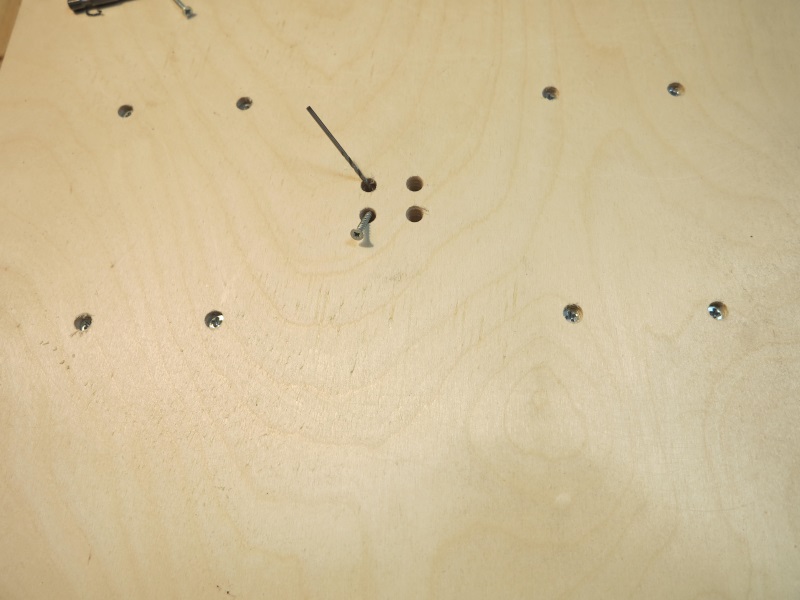
Figure 8. Fastening the running nut.
4 Assembling the machine portal.
For assembly you will need:
1) a set of milled parts for assembling a moving table
2) steel linear guides with a diameter of 16mm (2 pcs)
3) linear bearing LM16UU(4pcs)
4) lead screws for the Modelist 2030 milling machine - M12 (pitch 1.75mm) with ends processed at d=8mm and d=5mm.
For the Modelist 3030 milling machine - TR12x3 trapezoidal screws (3mm pitch) with ends processed at d=8mm.
5. radial bearings for fastening the lead screws - (2 pcs.)
6. running nut made of graphite-filled caprolon - (- 1 pc.)
4.1 Secure the side of the portal, Figure 9.

Figure 9. Assembly of the machine portal.
4.2 Insert the lead screw with nut into the Z-axis carriage frame, Figure 10.

Figure 10. Installing the lead screw.
4.3 Insert linear guides, Figure 11.

Figure 19 Fastening the lead screw “in space”.
4.4 Secure the second side of the portal, Figure 11.

Figure 11. Installation of the second side of the portal
If the lead screw is not clamped by the parts of the base of the moving table and there is play along the axis, use a washer with a diameter of 8 mm.
4.5 Install and secure the rear wall of the Z carriage, Figure 12.

Figure 12. Fastening the rear wall of the Z carriage.
4.6 Secure the caprolon running nut with 3x20 screws from the kit, Figure 13.

Figure 13. X-Axis Running Nut Attachment.
4.7 Secure the rear wall of the portal, Figure 14, using 3x25 screws from the kit. 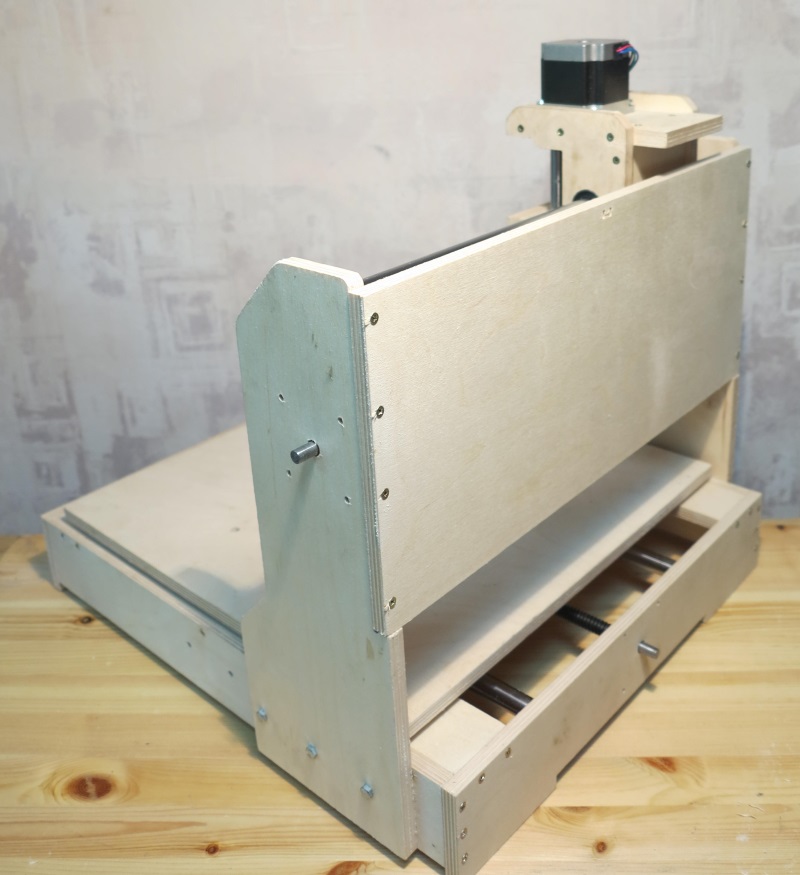
Figure 14. Fastening the rear wall of the portal.
5 Installation of stepper motors.
To install stepper motors, use fastening parts from a set of CNC milled parts for assembling Nema23 stepper motor supports for the Modelist3030 milling machine.

Figure 15. Installation of stepper motors.
Install 5x8mm couplings to connect the motor shaft to the lead screw. Attach the stepper motors to the machine; for fastening, use the M4x55 screw from the kit, Figure 15.
6 Attach the controller to the back wall of the milling and engraving machine, and connect the motor terminal blocks to it.
7 Installation of the router.
The router is fastened to the tool neck or body. The standard neck diameter of household routers is 43mm. Spindle diameter 300W - 52mm, fastening to the body. To install, assemble the router mount, the mounting details are in Figure 16. Use the 3x30mm screw from the kit.
Figure 16 43mm spindle mount
Figure 17 Spindle with mounting on a CNC machine
When installing Dremel-like tools (engravers), you will also need to additionally fasten the engraver body to the Z carriage with a clamp, Figure 18.

Figure 18 Attaching the engraver to a milling machine.
It is possible to install a nozzle for connecting a vacuum cleaner