The operating principle of a combined cycle plant. Great encyclopedia of oil and gas
Schemes and indicatorsgas turbinepower plant installations
Gas turbine power plants in the USSR received limited distribution as independent power plants. Serial gas turbine units (GTUs) have low efficiency and, as a rule, consume high-quality fuel (liquid or gaseous). With low capital costs for construction, they are characterized by high maneuverability, which is why in some countries, for example in the USA, they are used as peak power plants. Gas turbines have increased noise characteristics compared to steam turbines, requiring additional sound insulation of the engine room and air intake devices. The air compressor consumes a significant proportion (50-60%) of the gas turbine's internal power. Due to the specific power ratio of the compressor and gas turbine, the range of changes in the electrical load of the gas turbine unit is small.
The thermal cycle representing this machine is the Brayton cycle. The air is removed from the atmosphere and compressed, and then enters the combustion chamber, where it mixes with fuel and ignites. Hot gases, combustion products, flow through the turbine. There they expand and move the shaft that drives the turbine compressor and alternator.
The currently developed gas turbine design is based on a multi-stage axial compressor, an internal combustion chamber and an expansion turbine, all of which are very compact, giving the idea of a unitary equipment. The toy was pure mental seduction because it was unknown that it had never been built. Among them, the third law declared that there is a balance between action and reaction: “for every action there will be a reaction of the same force and intensity, but in the opposite direction.”
The unit power of installed gas turbines does not exceed 100-150 MW, which is significantly less than the required unit power of large power units.
Most modern gas turbines operate according to a continuous fuel combustion scheme and are performed in an open (open) or closed (closed) cycle, depending on the type of fuel burned.
An example is shown in Figure 4. When the forces are balanced, they are equal in all directions. But by piercing the balloon or releasing the nozzle, an action occurs that unbalances the system. The first proper gas turbine was conceived by J. It consisted of a multi-stage axial compressor, a heat exchanger that preheated the air before entering the combustion chamber using exhaust gas from the turbine, and a multi-stage expansion turbine. Despite the excellent design, little success was due to poor compressor and turbine performance, low compression ratios and low maximum temperature achieved in accordance with the materials available at that time.
IN Open cycle gas turbine unit The fuel used is liquid low-sulfur gas turbine fuel or natural gas, which is supplied to the combustion chamber (Fig. 9.1). The air required for fuel combustion is purified in a complex air-purifying device (filter) and compressed in a compressor to a pressure of MPa. For getting set temperature gases in front of the gas turbine  °C, the required excess air (2.5-5.0) is maintained in the combustion chamber, taking into account the theoretical combustion temperature of the fuel, the type of fuel, the method of its combustion, etc. Hot gases are the working fluid in a gas turbine, where they expand, and then when temperature
  °C are released into the chimney.
Compression ratio was undoubtedly one of the problems that needed to be overcome for turbine development, since until efficient compressors were available, it was impossible to design turbines with outputs that would allow them to be developed. Griffith lays out the basic principles of his airfoil theory for the design of compressors and turbines, and it is from here that the design of axial compressors is developed. Griffith's airfoil theory is undoubtedly a major milestone in the development of gas turbines as we know them today, and the knowledge developed by Griffith enabled the development of high-performance compressors and turbines.
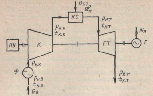
Rice. 9.1. Fundamental thermal diagram Open cycle gas turbine unit:
TO- air compressor;GT- gas turbine; G - electric generator; PU- starting device; F- air filter; KS- fuel combustion chamber
Closed cycle gas turbine unit(Fig. 9.2) allow the use of both solid and high-sulfur liquid fuel (fuel oil), burned in a combustion chamber where a working fluid heater, usually air, is installed. Including an air cooler in the circuit reduces the compression work in the compressor, and a regenerator increases the efficiency of the gas turbine unit. We have not yet seen the use of closed-cycle gas turbines with other working fluids (helium, etc.).
But its low weight and low volume characteristics meant that the development of turbines for aviation use began long before the outbreak of World War II. Meanwhile, Germany also developed its first aircraft jet engine parallel. However, with the highest achievable speeds came new aerodynamic problems that needed to be solved. Until the end of the war it was impossible for the aircraft to fly efficiently.
This widespread use of the engine, combined with new knowledge of aerodynamics, allowed the development of high-performance turbomachinery. Thus, from the 1960s, the use of the reactor became widespread, and by the 1970s, virtually all high-power aircraft were powered by turbines.
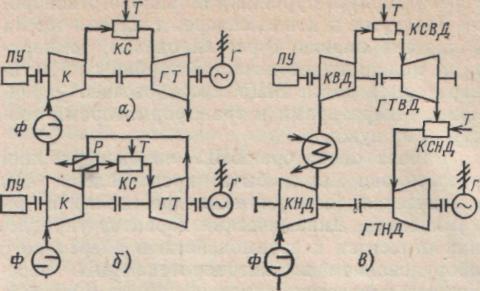
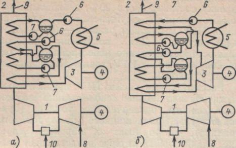
The main advantages of gas turbines for the power system are their mobility. Depending on the type of installation, its start-up and loading time is 5-20 minutes. Gas turbines are characterized by a lower specific cost (50-80% less than that of basic power units), a high degree of readiness for start-up, no need for cooling water, the possibility of rapid construction of thermal power plants with small dimensions of the power plant and insignificant environmental pollution. At the same time, gas turbine plants have a low efficiency of electricity production (28-30%), factory production They are more complex than steam turbines and require expensive and scarce fuels. These circumstances have also determined the most rational area for using gas turbines in the power system as peak-peak and usually autonomously started units using an installed capacity of 500-1000 h/year. For such installations, the preferred design is a single-shaft gas turbine unit of a simple cycle without regeneration or with a flue gas heat regenerator (Fig. 9.3, a, b). This scheme is characterized by great simplicity and compactness of installation, which is largely manufactured and installed at the factory. Power gas turbines, the operation of which is planned in the semi-basic part of the electrical load schedule, are economically justified to be carried out according to a more complex design scheme (Fig. 9.3, c).
Thus, gas turbine development has historically had three obstacles that have hindered and slowed its development. Compressor compression ratio and its performance. Resistance of materials for the use of high temperatures in the combustion chamber and in the first stages of the turbine.
To a lesser extent, it is difficult to control the entire system manually. The development of the gas turbine was only possible after the development of the axial compressor from improved aerodynamic concepts, which made it possible to provide high odds compression. The second of the pillars is technological innovation in materials, with the development of new monocrystalline alloys and ceramic coatings. This, along with in-depth study internal cooling of the blade made it possible to achieve very high temperatures both in the combustion chamber and in the first wheels of the blades.
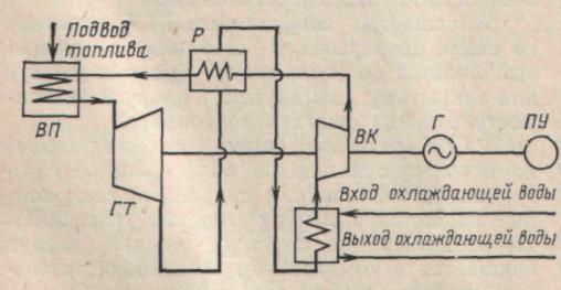
Rice. 9.2. Schematic diagram of a closed cycle gas turbine unit:
VP- air heater; GT- gas turbine; R- regenerator; VC-air compressor; G- electric generator; PU- starting device
The third key is the development of information technology. The use of computers has made it possible, on the one hand, to simulate certain conditions and behaviors in order to improve the design. On the other hand, this has made it possible to develop control systems that allow the operator to start, stop and monitor the main operating parameters of the machine minute by minute, as well as diagnose the technical condition of the equipment and predict future failures.
Figure 8: Compressor interior high pressure industrial turbine. The aerodynamic blade design is one of the keys to its excellent performance. In the 1970s, the use of turbines to generate electricity increased. The main elements of a gas turbine are five: air intake, compressor, combustion chamber, expansion turbine and rotor.
Rice. 9.3. Design diagrams of various types of gas turbine plants:
A- simple cycle gas turbine unit without regeneration; b - simple cycle gas turbine unit with flue gas heat regenerator; V- two-shaft gas turbine unit with two-stage fuel heat supply: T- fuel supply; KVD. Efficiency- high and low pressure air compressors; GTVD, GTND - high and low pressure gas turbines
The air intake system consists of all the elements necessary to allow air to enter the turbine under the most suitable conditions of pressure, temperature and purification. For this, it has several types of filters that will be responsible for eliminating dirt that can drag the air; and a number of systems that will condition the temperature to make it easier to greatest number air mass entered the turbine.
The combustion air intake is controlled by changing the angle of the initial wheels of the compressor blades. At higher angles, more air enters the compressor, and therefore the turbine. This method is used to improve the part load behavior of a gas turbine, as will be shown below.
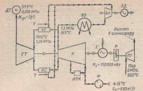
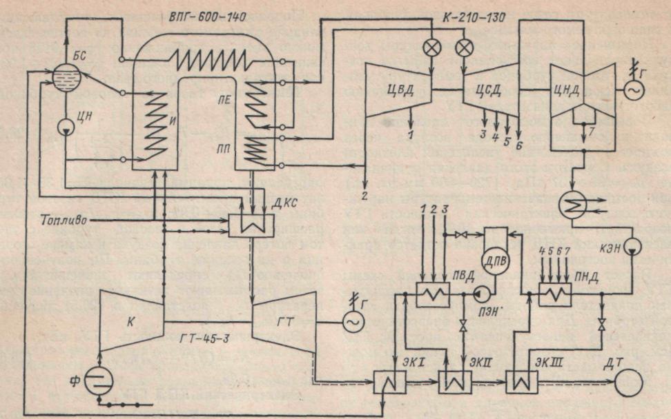
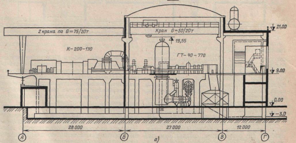
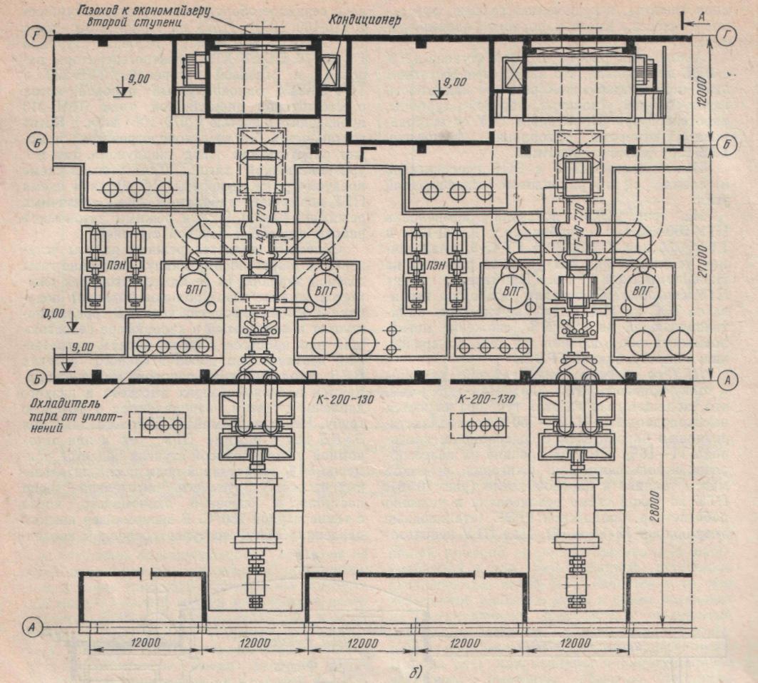
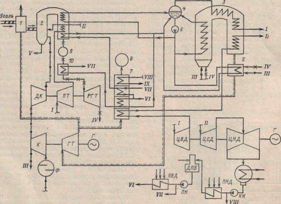
In the Soviet Union, gas turbine power plants operate with gas turbines of the types GT-25-700, GT-45-3, GT-100-750-2 and others with an initial gas temperature in front of the gas turbine of 700-950 °C. The Leningrad Metal Plant has developed designs for a new series of gas turbine units with a capacity of 125-200 MW at an initial gas temperature of 950, 1100 and 1250 °C, respectively. They are made according to a simple design with an open cycle of operation, single-shaft, without a regenerator (Table 9.1). The thermal diagram of the gas turbine unit GT-100-750-2 LMZ is shown in Fig. 9.4,a, and the layout of a power plant with such turbines is shown in Fig. 9.4, b. These gas turbine units are operated at the Krasnodar Thermal Power Plant, at the State District Power Plant named after. Klasson Mosenergo, at the peak thermal power plant in Inota, Hungarian People's Republic, etc.
Some of the compressor air is used to cool the blades and combustion chamber, so that approximately 50% of the air mass is used for this purpose. It constantly burns flammable gas together with air. Due to the high temperatures that can be reached during combustion, as well as to shorten the life of the chamber components, a high excess of air is used, using 300 to 400% of the theoretical air required, on the one hand the flame temperature can be reduced, and on the other hand the other is to cool the hottest parts of the chamber.
Table 9.1
|
GTU indicators |
|||||
|
Gas turbine installation |
Electric power, MW |
Air consumption ha through com- pressor, kg/s Part of the air coming from the compressor is directed directly into the walls of the combustion chamber to maintain its temperature at relatively low values. The other part circulates inside the turbine blades, leaving holes at the edges that create a film on the surface of the blades. The turbine contains the energy contained in the combustion gases, in the form of pressure and elevated temperature, occurs at mechanical power. As stated above, a significant portion of this power is directly absorbed by the compressor. This high temperature means that the energy they contain can be used to improve the operation of a turbine or, more commonly, to produce steam in a recovery boiler. This steam is then injected into a steam turbine, achieving an overall increase in yield equal to or even greater than 55%. |
Degree of compression tia in compression |
Initial gas temperature, |
Electric |
|
GT-100-750-2M* Natural gas is perceived as a good source of electricity for a number of reasons, both economic, operational and environmental: it is low risk, produces less carbon emissions than other fossil fuels, gas plants can be built relatively quickly, in some cases approximately in two years, unlike nuclear plants, which can take much longer to build. The International Energy Agency forecasts that natural gas will continue to increase its share of the global energy mix, growing at 2% per year to date. Natural gas accounts for a quarter of the world's primary energy use and has represented very significant growth in last years, which is largely due to its use as a generator of electricity through thermal power plants, whether new or adapted. | |||||
|
"General Electric" | |||||
* Turbines and compressors are twin-shaft; the shaft with the turbine and high-pressure compressor has an increased rotation speed.
** Working on natural gas(liquid gas turbine fuel).
Natural gas installations flexible, both technically and economically, respond quickly to peak demand and combine perfectly with intermittent renewable options such as wind power. Several demand peaks occurring throughout the month have a significant multiplier effect on the cost of electricity supplied, so having an energy source such as gas that can handle these peaks is a significant benefit.
These benefits are recognized worldwide, and more and more more projects All over the world they are trying to use natural gas to produce electricity. The top ten gas plants are now dominated by Japan, leading to a major turnaround for the technology following the Fukushima disaster.
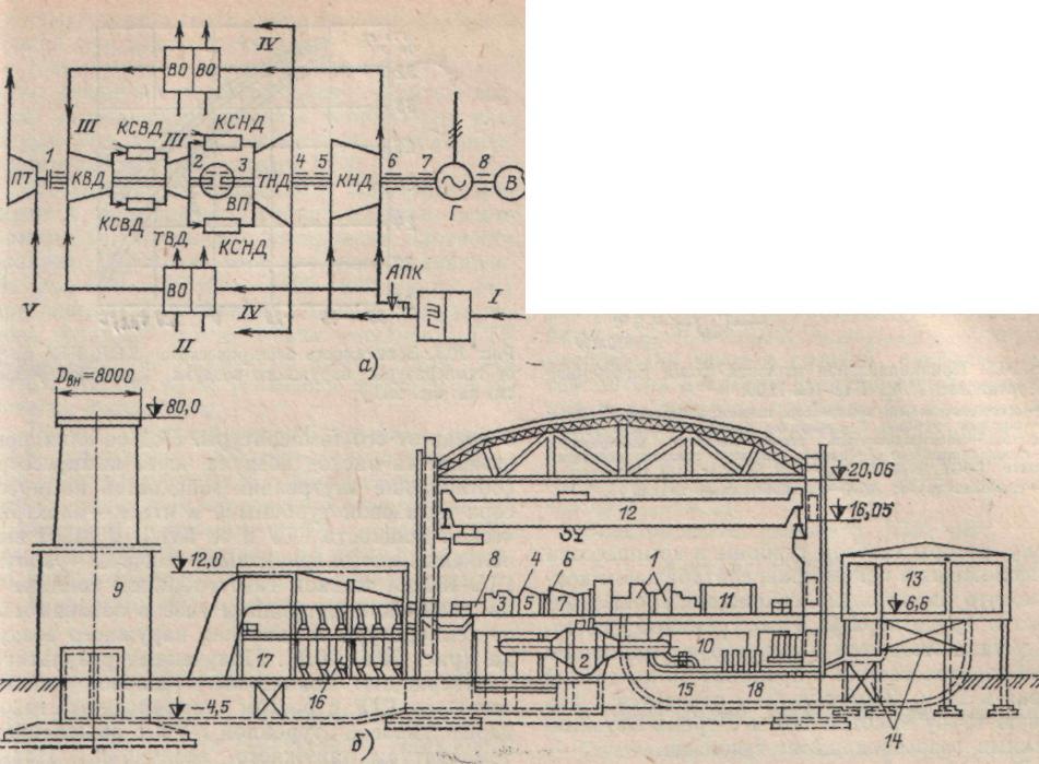
Rice. 9.4. Gas turbine unit GT-100-750-2 LMZ:
A- thermal diagram: 1-8 - GTU bearings; / - air from the atmosphere; II - cooling water; III- fuel (natural gas); /V - exhaust gases; V - steam to the starting turbine (p = 1.2 MPa, t = 235 ° C); GSH- noise suppressor; LPC - low pressure compressor; IN- air coolers; KVD- high pressure compressor; KSWD - high pressure combustion chamber; theater of operations- high pressure turbine; KSND - low pressure combustion chamber; TND- low-pressure turbine; VP- internal bearing; IN- pathogen; PT- starting turbine; agro-industrial complex - anti-surge valves behind pressure pump; b - layout (cross section):/ - LPC; 2-VO; 3 - pressure build-up; 4 - KSVP; 5 - theater; 6 - KSND; 7-TND; 8 - PT; 9 - chimney; 10 - anti-surge valve (APV); L-electric generator (G); 12- overhead crane; 13- air purification filters; 14 - noise mufflers; 15 - oil pumps of the control system; 16- district heating heaters; /7 - dampers on exhaust ducts; 18 - oil coolers
Thus, Japan puts six plants in the classification, Russia two, and Taiwan and Uzbekistan the 10 largest gas plants in the world. The plant is operated by Tohoku Electric Power Company. Under the management of the Chubu Electric Power Company, the plant began operating for the first time this year.
The Chita power plant currently consists of six liquefied natural gas units, four of which operate in a combined cycle. Kostroma Power Plant is a gas plant located near Volgorechensk in Russia. The latter is today the largest gas division in the world. The station also has a height of 320 m, one of the highest in the world.
Liquid gas turbine fuel used for domestic gas turbines is subjected to filtration and washing to remove alkali metal salts at the power plant. A magnesium additive is then added to the fuel to prevent vanadium corrosion. According to operational data, such fuel preparation contributes to long work gas turbines without contamination and corrosion of the flow path.
Syrdarya Power Plant is a natural gas production plant located in Shirin, Uzbekistan. The plant has three chimneys, the highest of which is 350 meters. This is an extremely efficient and unique power converter equipment that uses auger expander technology to generate electricity by using gas or steam pressure reducing pressure control stations.
Generating equipment made from natural gas. The gas pressure reduction generator is an economically viable energy recovery solution applicable to natural gas pressure control stations. We understand that our equipment is truly revolutionary in meeting the demand for renewable energy.
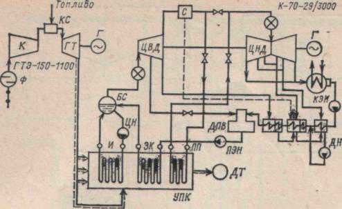
The Rostov branch of ATEP has developed a standard design for a peak gas turbine power plant with a gas turbine unit GTE-150-1100. In Fig. Figure 9.5 shows a basic thermal diagram of such a gas turbine unit, designed to burn liquid gas turbine fuel or natural gas. The gas turbine unit is made in a simple manner open circuit, the rotors of the gas turbine and compressor are located in one transportable housing, which significantly reduces installation time and labor costs. Gas turbine units are installed transversely in the machine room of a power plant with a span of 36 and a block cell of 24 m. Flue gases are discharged into a chimney 120 m high with three metal gas exhaust shafts.
Rice. 9.5. Schematic thermal diagram of the gas turbine unit LMZ GTE-150-1100:
VC- auxiliary compressor for pneumatic fuel atomization: PT- steam turbine; R- gearbox of the accelerating device block; ED - auxiliary compressor motor GT- gas turbine; T- supply of liquid fuel corresponding to GOST 10743-75,  = 42.32 MJ/kg (10,110 kcal/kg) DT- chimney; agro-industrial complex- anti-surge valve
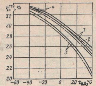
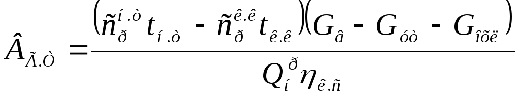
An important feature of gas turbine plants is the dependence of their performance on the parameters of the outside air, and primarily on its temperature. Under its influence, the air flow through the compressor, the ratio of the internal powers of the compressor and gas turbine, and, ultimately, the electrical power of the gas turbine and its efficiency change. At MPEI, multivariate calculations of the operation of GTE-150 on liquid gas turbine fuel and on Tyumen natural gas were performed depending on the temperature and pressure of the outside air (Fig. 9.6, 9.7). The results obtained confirm the increase in the thermal efficiency of gas turbines with increasing gas temperature in front of the gas turbine  and with a decrease in outside air temperature
  . Temperature rise from =800°C to = =1100°C increases the electrical efficiency of the gas turbine unit by 3% at = -40 °C and by 19% at = 40 °C. Reducing the outside air temperature from +40 to -40°C leads to a significant increase in the electrical power of the gas turbine unit. For different initial temperatures this increase is 140-160%. To limit the growth of gas turbine power when the outside temperature decreases and taking into account the possibility of overloading the electric generator (in the case under consideration, type TGV-200), it is necessary to influence either the temperature of the gases in front of the gas turbine, reducing fuel consumption (curves 4
in Fig. 9.6 and 9.7), or on the outside air temperature, mixing a small amount of exhaust gases (2-4%) to the air sucked in by the compressor. Constant flow air in the load range of 100-80% can also be maintained by covering the inlet guide vane (IVA) of the gas turbine compressor.
. Temperature rise from =800°C to = =1100°C increases the electrical efficiency of the gas turbine unit by 3% at = -40 °C and by 19% at = 40 °C. Reducing the outside air temperature from +40 to -40°C leads to a significant increase in the electrical power of the gas turbine unit. For different initial temperatures this increase is 140-160%. To limit the growth of gas turbine power when the outside temperature decreases and taking into account the possibility of overloading the electric generator (in the case under consideration, type TGV-200), it is necessary to influence either the temperature of the gases in front of the gas turbine, reducing fuel consumption (curves 4
in Fig. 9.6 and 9.7), or on the outside air temperature, mixing a small amount of exhaust gases (2-4%) to the air sucked in by the compressor. Constant flow air in the load range of 100-80% can also be maintained by covering the inlet guide vane (IVA) of the gas turbine compressor.
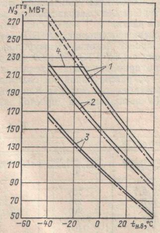
Rice. 9.6. Dependence of electric power of gas turbine unit  on outside temperature
  :
:
1-=1100°C; 2- = 950°C; 3 - = 800 °C; 4- = ; - operation of gas turbine units on natural gas; operation of gas turbine units on liquid fuel
Rice. 9.7. Dependence of the electrical efficiency of a gas turbine unit  on outside temperature
(for symbols see Fig. 9.6)
on outside temperature
(for symbols see Fig. 9.6)
The change in electrical efficiency towards its decrease is especially significant at outside air temperatures above 5-10 °C (Fig. 9.7). With an increase in outside air temperature from +15 to +40 C, this efficiency decreases by 13-27% depending on the temperature of the gases in front of the gas turbine and the type of fuel burned.
An increase in external air temperature increases the excess air coefficient behind the gas turbine and the temperature of the exhaust gases, which contributes to the deterioration of the energy performance of the gas turbine plant.
An increase in atmospheric pressure leads to an increase in air flow through the compressor due to an increase in air density. As this pressure increases in the range  kPa (720-800 mmHg) at a constant outside air temperature, the electrical power of the gas turbine unit increases by approximately 10%, while the electrical efficiency of the installation remains almost constant.
The calculation of the basic thermal diagram of a gas turbine is carried out by sequentially calculating the performance indicators of the compressor and gas turbine. To determine the energy indicators of a single-stage simple gas turbine unit (see Fig. 9.1), the following dependencies can be used with sufficient accuracy:
Power, kW, compressor drive
Where ![]() - specific heat capacity of air, kJ/(kg-K);
- specific heat capacity of air, kJ/(kg-K);  - outside air temperature, K;
  - degree of air compression in the compressor;
  - isentropic index;
  - polytropic compressor efficiency;
  - air flow through the compressor, kg/s.
Fuel consumption in the combustion chamber, kg/s,
Where ![]() - air temperature behind the compressor, °C;
- air temperature behind the compressor, °C;  - air leakage through the compressor end seals, kg/s; - air consumption for cooling the gas turbine blade apparatus, kg/s;
  - Efficiency of the combustion chamber.
Gas turbine internal power, kW,
Enthalpy of gases  , kJ/kg, at temperatures at the inlet and outlet of the gas turbine can be approximately determined by the expression
The correction factor, which takes into account the effect of burned fuel on the composition of gases, can be estimated approximately:  =1.0125 when burning liquid fuel,
  when burning natural gas.
Temperature of gases behind the gas turbine, °C,
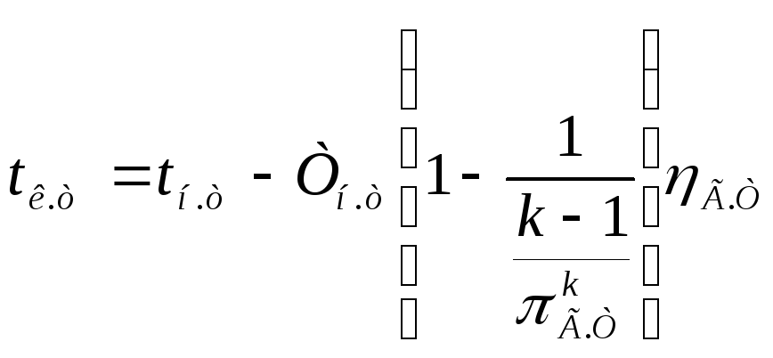
determined by first taking  ; internal relative efficiency of a gas turbine
  ;
; - degree of expansion of gases in a gas turbine, taking into account air pressure losses in the combustion chamber and at the turbine exhaust. Based on the received value
  determine the value
  ,
and then calculate the true temperature value t k.t. ,
substituting into (20.5) the values
,
and then calculate the true temperature value t k.t. ,
substituting into (20.5) the values
k=0.5(k n.t. - k k.t. ) .
Electric power of the gas turbine unit, kW,
Where ![]() .
.
Electrical efficiency of gas turbine unit
 .
.
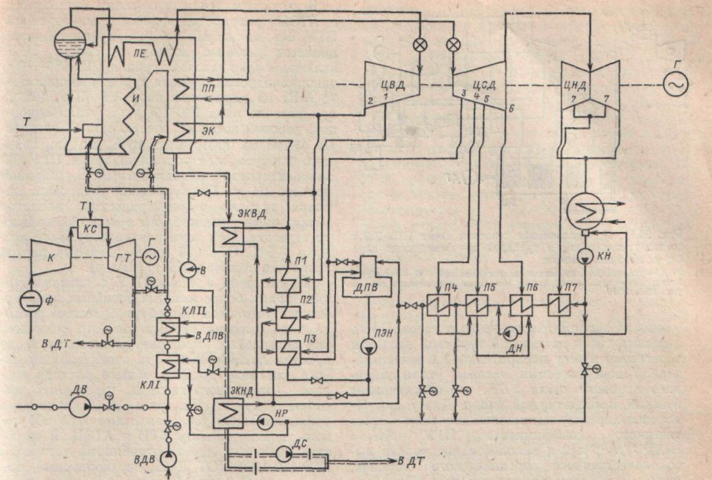
Combined-cycle power plants
The combination of steam turbine and gas turbine units, united by a common technological cycle, is called a combined cycle plant (CCGT) of a power plant. Combining these units into a single unit makes it possible to reduce heat loss from the exhaust gases of a gas turbine unit or steam boiler, use gases behind gas turbines as a heated oxidizer when burning fuel, obtain additional power due to partial displacement of the regeneration of steam turbine units, and ultimately increase the efficiency of a combined cycle power plant in terms of compared with steam turbine and gas turbine power plants.
The use of CCGT units for today's energy sector is the most effective remedy significant increase in thermal and overall efficiency of fossil fuel power plants. The best operating CCGT units have an efficiency of up to 46%, and those being designed - up to 48-49%, i.e. higher than in the designed MHD installations.
Among the various CCGT options, the following schemes are most widespread: CCGT with a high-pressure steam generator (HPSG), CCGT with gas turbine gas discharge into the furnace of a steam boiler, CCGT with a recovery steam boiler (UPB), semi-dependent CCGT, CCGT with intra-cycle gasification solid fuel.
Developed at NPO TsKTI CCGT unit with high-pressure steam generator operate on natural gas or liquid gas turbine fuel (Fig. 9.8). The air compressor supplies compressed air to the annular gap of the housing HSV and into an additional combustion chamber DKS, where its temperature rises. Hot gases after burning fuel in the combustion chamber have a pressure of 0.6-1.2 MPa, depending on the air pressure behind the compressor, and are used to generate steam and superheat it. After the intermediate superheater - the last heating surface HSV- gases with a temperature of approximately 700 °C enter an additional combustion chamber, where they are heated to 900 °C and enter the gas turbine. The gases exhausted in the gas turbine are sent to a three-stage gas-water economizer, where they are cooled by feed water and the main condensate of the steam turbine. This connection of economizers ensures a constant temperature of the flue gases of 120-140 ° C before they exit into the chimney. At the same time, in such a CCGT there is a partial displacement of regeneration and an increase in the power of the steam turbine unit.
BS - separator drum; PE- steam superheater; PP - intermediate superheater; AND- evaporative heating surfaces; CN- circulation pump; EK1 - EKSH- gas-water economizers for heat recovery from gas turbine exhaust gases; DPV - feed water deaerator; DKS- additional combustion chamber
A high-pressure steam generator is a common fuel combustion chamber for a steam turbine and a gas turbine unit. A special feature of such a CCGT is that the excess gas pressure in the circuit makes it possible not to install smoke exhausters, and the air compressor replaces the blower fan; there is no need for an air heater. Steam from the HPG is sent to a steam turbine unit, which has a conventional thermal circuit.
A significant advantage of this installation is the reduction in size and mass indicators of the HSV, operating at a pressure in the gas path of 0.6-1.2 MPa. The high-pressure steam generator is entirely manufactured in the factory. In accordance with transportation requirements, the steam production of one HPG housing does not exceed 350-10 3 kg/h. The steam generator VPG-650-140-545/545 PO TKZ, for example, consists of two buildings. Its flues are shielded with welded gas-tight panels made of finned pipes.
It is advisable to use CCGT units with HPG at moderate gas temperatures in front of the gas turbine unit. As this temperature increases, the proportion of heat transferred by the gases to the heating surface of the high-pressure steam generator decreases.
Autonomous operation of the steam stage of a CCGT unit with HPG is impossible, which is a disadvantage of this scheme, which requires equal reliability of the gas turbine unit, steam turbine, and steam generator. The use of gas turbines with built-in combustion chambers (for example, GTE-150) is also unacceptable.
The use of CCGT units with HPG is promising in schemes with intra-cycle coal gasification.
In Fig. Figure 9.9 shows the layout of the PGU-200-250 with turbines K-160-130 and GT-35-770 or K-210-130 and GT-45-3. A similar installation has been successfully operating at the Nevinnomyssk State District Power Plant for a number of years. The use of such CCGTs can provide fuel savings at thermal power plants by 15%, a reduction in specific capital investments by 12-20%, and a reduction in the metal consumption of equipment by 30% compared to a steam turbine power plant.
CCGT with gas discharge gas turbine into the furnace of a steam boiler are characterized by the fact that the exhaust gases of the gas turbine are a highly heated (450-550°C) ballasted oxidizer with an oxygen content of 14-16%. For this reason, it is advisable to use them for burning the bulk of the fuel in a steam boiler (Fig. 9.10). A CCGT unit according to this scheme has been implemented and is successfully operating at the Moldavian State District Power Plant (station power units No. 11 and 12). Serial equipment was used for the CCGT unit: steam turbine K-210-130 POT LMZ with steam parameters of 13 MPa, 540/540 °C, gas turbine GT-35-770 POAT HTZ, electric generators of steam and gas stages TGV-200 and TVF-63- 243, single-shell steam boiler with natural circulation type TME-213 with a capacity of 670*10 3 kg/h. The boiler is supplied without an air heater and can operate both “under pressurization” and with balanced draft. For this purpose, the scheme provides smoke exhausters DS.This scheme The CCGT allows operation in three different modes: CCGT mode and autonomous operation modes of the gas and steam stages.
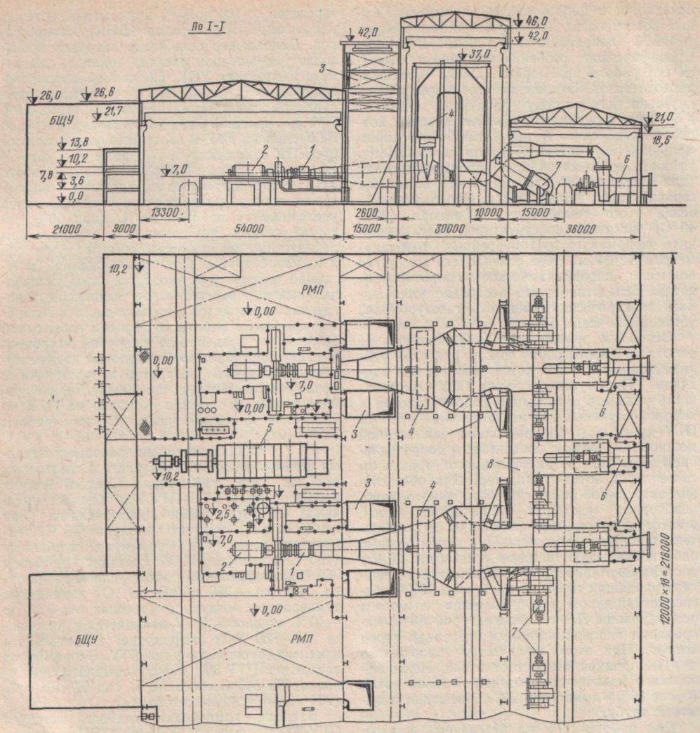
Rice. 9.9. Layout of the main building of PGU-250 with a high-pressure steam generator:
A- cross section; b - plan; for designations see fig. 9.8
The main operating mode of the installation is the steam-gas cycle. The exhaust gases of the gas turbine (liquid gas turbine fuel is burned in its combustion chamber) are supplied to the main burners of the boiler. The burners also receive the air heated in the heater, which is missing for the combustion process and is pumped by an additional air fan. Airborne Forces The steam boiler exhaust gases are cooled in high and low pressure economizers and then sent to the chimney. Via high pressure economizer EKVD Both in the CCGT mode and during autonomous operation of the steam stage, approximately 50% of the feed water is supplied after the feed pumps. Then all the feed water enters the main boiler economizer at a temperature of 250°C. In low pressure economizer EKND the main turbine condensate arrives after PND5(at loads greater than 50%) or after PND4(at loads below 50%). In this regard, the regenerative extractions of the steam turbine are partially unloaded, and the steam pressure in its flow path increases slightly; increased steam flow into the turbine condenser.
During autonomous operation of the steam stage, the air required for combustion of fuel in the boiler is supplied by a blower fan Far East into heaters, where it is heated to 180 °C and then sent to the burners. The steam boiler operates under vacuum created by smoke exhausters DS. When the gas stage operates autonomously, the exhaust gases are directed into the chimney.
The ability to operate the CCGT unit in various modes is ensured by the installation of an automatically controlled system of quick-closing gas-air dampers (dampers) large diameter, mounted on gas ducts to disconnect one or another element of the installation. This increases the cost of the circuit and reduces its reliability.
With an increase in the temperature of the gases in front of the CCGT gas turbine and at a lower degree of air compression in the compressor, the oxygen content in the exhaust gases of the gas turbine decreases, which requires the supply of additional air. This leads to an increase in the volume of gases passing through the convective heating surfaces of the steam boiler, as well as heat loss with exhaust gases  .
The energy consumption for driving the blower fan also increases. When solid fuel is burned in a boiler, heated air is used in the dust preparation system.
.
The energy consumption for driving the blower fan also increases. When solid fuel is burned in a boiler, heated air is used in the dust preparation system.
Operating experience of the PGU-250 at the Moldavian State District Power Plant has shown that its efficiency largely depends on the load of the steam and gas stages. The specific consumption of equivalent fuel at a rated load of 240-250 MW reaches 315 g/(kWh).
Combined-cycle power plants of this type are widespread abroad (USA, England, Germany, etc.). The advantage of this type of CCGT is that it uses a steam boiler of a conventional design, in which it is possible to use any type of fuel, including solid fuel. In the combustion chamber of a gas turbine unit, no more than 15-20% of the fuel required for the entire gas turbine unit is burned, which reduces the consumption of its scarce varieties. The start-up of such a CCGT unit usually begins with the start-up of a gas turbine unit, the use of the heat of the exhaust gases of which makes it possible to increase the steam parameters in the steam boiler and reduce the amount of fuel consumed to start up the steam turbine equipment.
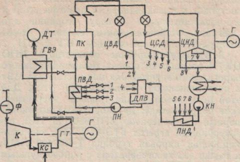
PE- live steam superheater; PP-intermediate superheater; EC, EKVD, EKND- economizers: main, high and low pressure; P1–P7 - steam stage regeneration system heaters; DPV- feed water deaerator; PEN, KN, DN- feed, condensate, drainage pumps; HP- pump for recirculating the main condensate to the EKND; Far East, Airborne Forces- blower and additional air fans ; KL1,KL11- heaters of the first and second stages ; IN- injection feed water from the intermediate stage of the PEN; DS- smoke exhauster
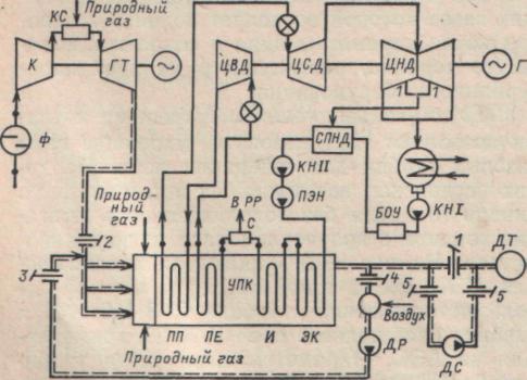
CCGT with recycling Steam boilers allow the exhaust gases of gas turbines to be used to generate steam. In such installations, it is possible to implement a purely binary cycle without additional combustion of fuel to produce steam of low parameters. In Fig. Figure 9.11 shows the proposed MPEI diagram of such a CCGT unit, which uses a gas turbine GTE-150-1100 and a turbine saturated steam K-70-29, used at nuclear power plants. Steam parameters in front of the turbine are 3 MPa, 230 °C. According to the conditions of permissible temperature differences between gases and steam and the most complete use of the heat of exhaust gases, the intermediate superheater is made of gas-steam and is located behind the economizer along the flow of gases. Part of the flue gases behind the gas turbine is introduced into the cut between the evaporation and economizer heating surfaces of the recovery steam boiler Code of Criminal Procedure, which provides the required temperature pressure. Such installations are characterized high values energy coefficient of CCGT units and the use of only high-quality organic fuel, mainly natural gas. At an outside air temperature of +15°C and a flue gas temperature of 160°C, the total electrical power of the CCGT unit is approximately 220 MW, the efficiency is 44.7%, and the specific fuel consumption is 281 g/(kWh).
Rice. 9.11. Schematic thermal diagram of a PGU-220 with a waste heat boiler and a turbine running on saturated steam without afterburning fuel:
Code of Criminal Procedure- recovery boiler (steam generator); C - moisture separator; DN- drainage pump; For other designations, see Fig. 20.8, 20.10
The All-Union Thermal Engineering Institute and ATEP have developed a version of a maneuverable CCGT without afterburning fuel before the recovery steam boiler. The CCGT includes one gas turbine GTE-150-1100, a single-cylinder steam turbine with a power of 75 MW for steam parameters of 3.5 MPa, 465 °C with a steam flow of 280-10 3 kg/h, a recovery steam boiler with a heating surface of 40-10 3 m 2 of finned pipes. The module of the main building of the power plant of such a PGU-250 is designed to be single-span with a span width of 24 m. The gas turbine unit, steam turbine and electric generator between them are mounted in the form of a single-shaft unit. At an outside air temperature of +5 °C, the PGU-250 has a specific fuel consumption of 279 g/(kWh).
The use of more powerful serial steam turbine units in a CCGT scheme with waste heat boilers will require a greater consumption of high-parameter steam. This is possible by increasing the gas temperature at the boiler inlet to 800-850 °C due to additional combustion of up to 25% of the total fuel consumption (natural gas) in the boiler burner devices. In Fig. 20.12 shows a basic thermal diagram of a PGU-800 of this type according to the VTI and ATEP project. It includes two gas turbine units GTE-150-1100 POT LMZ, a two-case recovery steam boiler ZiO with a total steam output of 1150-10 3 kg/h and steam parameters of 13.5 MPa, 545/545 °C, steam turbine K-500- 166 POT LMZ. This scheme has a number of features. The regenerative bleeds of the turbine (except for the last one) are plugged; The regeneration system has only mixing HDPE. A deaerator-free scheme with deaeration of turbine condensate in the condenser and in the mixing heater was used. Condensate with a temperature of 60 °C is supplied by two feed pumps PE-720-220 to the boiler economizer. The absence of regenerative steam extraction increases its passage into the turbine condenser, the electrical power of which is therefore limited to 450 MW.
A direct-flow U-shaped recovery steam boiler consists entirely of convective heating surfaces. After the gas turbine unit, exhaust gases in the amount of 680 kg/s with a temperature of 430-520 ° C and an oxygen content of 14-15.5% enter each of the UPC buildings. Natural gas is burned in the main burners of the UPC. and the temperature of the gases in front of the heating surfaces of the boiler rises to 840-850 °C. Combustion products are sequentially cooled in steam superheaters (intermediate and main), in evaporation and economizer heating surfaces and at a temperature of ~125°C are sent to the chimney. A specific feature of the boiler is its operation at a significant mass flow of gases. The ratio of its steam output to the consumption of combustion products is 5-6 times lower than that of conventional steam boilers of power units. As a result, the minimum temperature difference moves from the area of the intermediate superheater (for a once-through gas-oil boiler) to the hot end of the economizer. The small value of this temperature difference (20-40 °C) forced the UPC designers to make an economizer from finned pipes with a diameter of 42X4 mm, which reduced its weight, but increased the aerodynamic resistance of the boiler. As a result, the electrical power of the gas turbine unit and the entire CCGT decreased slightly.
The main mode of the PGU-800 is its operation in the steam-gas cycle, while the recovery steam boiler operates under pressurization. The advantage of such CCGTs is the possibility of autonomous operation of gas and steam stages. Independent operation of the CCGT unit occurs at a slightly reduced power due to the increased exhaust resistance carried out by the transit of gases through the waste heat boiler. To ensure autonomous operation of the steam turbine unit, some complication of the circuit is necessary, which must additionally include dampers and smoke exhausters. In this operating mode, the gates are closed 1 and 2 (Fig. 9.12) and open the gates 3 -5. The main amount of boiler flue gases (about 70%) is enriched with air and recirculation using a smoke exhauster DR with a temperature of 80 °C are sent to additional burners in front of the boiler. At the same time, the amount of fuel burned in the CPC triples. Unused amount of boiler flue gases (about 30%) by smoke exhauster DS thrown into the chimney.
To operate a CCGT unit using reserve liquid gas turbine fuel, it is necessary to provide in the thermal circuit for additional heating of water to 130-140°C in order to avoid corrosion of the tail heating surfaces. This operating mode will therefore be less economical.
CCGT units with recovery steam boilers are highly maneuverable. They are designed for approximately 160 launches per year; The start-up time after a standstill of 6-8 hours is 60 minutes, and after a stop for 40-48 hours it is 120 minutes. When unloading the CCGT unit, first of all, the load on the gas turbine units is reduced from 100 to 80% by covering the inlet guide vanes (IGUs) of the compressors. Further reduction of the load is carried out by reducing the consumption of fuel burned in the burners of the UPC, reducing the steam production of the latter while maintaining the temperature of the gases in front of the gas turbines. When 50% of the rated load of the CCGT unit is reached, one of the gas turbine units and the corresponding CCP housing are switched off. With a decrease in the load of the steam stage and the steam production of the UPC, a redistribution of temperatures occurs along the path, and the temperature of the flue gases increases to 170-190 ° C (at 50% boiler load). This temperature increase is unacceptable due to the operating conditions of the smoke exhausters and chimney. To maintain the permissible temperature of the flue gases, the recovery steam boiler at reduced loads is transferred from direct-flow to separator mode of operation with the discharge of excess heat into the condenser of the steam turbine. The steam turbine installation design includes a built-in separator and a pilot expander. The transition to the separator mode increases the fuel consumption of the CCGT unit by 5-10% compared to the direct-flow mode of operation.
It is advisable to install CCGT units with utilization steam boilers in gas-bearing regions of Western Siberia, Central Asia, etc. According to VTI, CCGT-800 has high energy performance. At an outside air temperature of +5°C, a gas temperature in front of the gas turbines of 1100°C, the power of the CCGT unit will be approximately 766 MW, and the specific consumption of equivalent fuel (net) will be 266 g/(kWh). With a change in air temperature in the range from +40 to -40 °C, the power of the CCGT unit changes in the range of 550-850 MW due to a significant change in the power of the two gas turbine units. Savings from the introduction of a PGU-800 instead of a conventional 800 MW power unit will amount to 5.7-10 6 rubles per year. (204-10 6 kg of standard fuel).
Rice. 9.12. Schematic thermal diagram of PGU-800 with waste heat boiler and afterburning of fuel:
1-5 - switchable gas-tight gates; DS- smoke exhauster; DR- smoke exhauster for gas recirculation; WITH- moisture separator; RR- kindling expander; AIDS- low pressure mixing heater
A variant of the layout of the main building of PGU-800 according to the design of VTI and ATEP is shown in Fig. 9.13. The estimated capital investment in the main building of the CCGT is 89 RUR/kW. Its construction will make it possible to save up to 9-10 6 kg of steel and up to 8-10 6 kg of reinforced concrete at a CPP with six PGU-800 units compared to the installation of six 800 MW gas-oil power units.
The combination of gas turbine and steam turbine plants using standard serial equipment is carried out in semi-independent combined cycle plant(Fig. 9.14). It is intended for use during peaks in the electrical load schedule and involves complete or partial shutdown of high-pressure steam heaters. As a result, its passage through the flow part of the steam turbine increases and an increase in steam stage power of approximately 10-11% is realized. The decrease in the temperature of the feed water is compensated by its additional heating in the gas-water economizer by the exhaust gases of the gas turbine. The temperature of the gas turbine exhaust gases decreases to approximately 190 °C. The total increase in peak power, taking into account the operation of the gas turbine unit, is 35-45% of the base power of the steam turbine unit. The specific consumption of standard fuel is close to the consumption at battery life this block .
1-gas turbine GTE-150-1100; 2 - electric generator GTU; 3-air intake into the gas turbine compressor; 4 – recovery steam boiler; 5 -steam turbine K-500-166; 6- smoke exhauster; 7 - blower fan; 8 -gas duct
Rice. 9.14. Schematic thermal diagram of a semi-independent combined cycle plant:
GVE- gas-water economizer; PC- steam boiler; For other designations, see Fig. 9.8.
It is advisable to install semi-dependent CCGT units in the European part of the USSR. According to LMZ, the following combinations of steam and gas turbines are recommended: 1 X K-300-240 + 1 X GTE-150-1100; 1 x K-500-130+ 1 x GTE-150-1100; 1 X K-1200-240 + 2 X GTE-150-1100, etc. The increase in estimated capital investments in a gas turbine unit will be about 20%, and the equivalent fuel savings in the power system when operating a CCGT unit in peak mode is (0.5-1. 0) X X10 6 kg/year. To obtain peak power, it is promising to use heating plants in the scheme of semi-independent CCGT units.
The considered CCGT schemes assume partial or full use high-quality organic fuel (natural gas or liquid gas turbine fuel), which hinders their widespread implementation. Of significant interest are the various schemes of combined cycle gas plants developed by CKTI with high-pressure steam generators and intra-cycle gasification of solid fuel (Fig. 20.15), which make it possible to convert the combined cycle gas plants entirely to coal.
Rice. 9.15. Schematic thermal diagram of a CCGT unit with HPG and in-cycle coal gasification:
/- fuel drying ; 2 - gas generator; 3 - high-pressure steam generator (HPG); 4 - drum separator; 5 - additional HPG combustion chamber; 6- HSV circulation pump; 7-economizer for recovery of heat from exhaust gases of a gas turbine; 8-chimney; 9- scrubber; 10- generator gas heater; DK- booster compressor; PT- steam drive turbine; RGT- expansion gas turbine; /- fresh steam; // - reheat steam ; /// - compressed air after the compressor; IV - purified generator gas; V - ash; VI- IX - turbine feed water and condensate
Pre-crushed coal (crushed coal 3-10 mm) is fed into the dryer for drying and through the oxidizer (to prevent slagging) into the gas generator. One of the scheme options is coal gasification in a gas generator with a “fluidized” bed using steam-air blast. Fuel gasification is ensured by supplying air to the gas generator after the booster compressor and steam from the “cold” intermediate superheating line. Air for gasification in an amount of approximately 3.2 kg per 1 kg of Kuznetsk coal is sequentially compressed in the main and booster compressors (the pressure increases by 10%) and, after mixing with steam, enters the gas generator. Coal gasification occurs at temperatures close to 1000 °C.
The generator gas is cooled, giving up its heat to the working fluid of the steam turbine part, then it is cleaned of mechanical impurities and sulfur-containing compounds and, after expansion in the expansion gas turbine (to reduce steam consumption by the drive turbine of the booster compressor), it enters the high-pressure steam generator and its additional combustion chamber for combustion . The rest of the thermal circuit coincides with the circuit of a conventional CCGT with HSV.
VNIPIenergoprom, together with NPO TsKTI, has developed a design for a combined heat and power unit with a capacity of 225 MW with in-cycle gasification of coal. For this purpose, standard power equipment was used: a double-casing high-pressure steam generator VPG-650-140 TKZ, a gas turbine unit GTE-45-2 KhTZ, a heating steam turbine T-180-130 LMZ, as well as two gas generators with steam-air blast GGPV-100-2 with a capacity 100 t/h of Kuznetsk coal. Technical and economic calculations have shown that, compared with a conventional steam turbine heating unit of 180 MW, the use of a combined cycle power unit allows increasing the specific electricity generation from thermal consumption by 1.5 times, ensuring fuel savings of up to 8%, significantly reducing harmful emissions into the atmosphere, and obtaining a total annual economic effect of 2.6-10 6 rubles. The considered combined cycle power unit will be used to create more powerful CCGT-1000 using coal from the Kuznetsk, Ekibastuz and Kansk-Achinsk basins.
Combined-cycle plants are widely used in the USA, Germany, Japan, France, etc. CCGT units mainly burn natural gas and liquid fuels of various types. The introduction of CCGT units was facilitated by the emergence of powerful gas turbine units (70-100 MW) with an initial gas temperature of 900-1100°C. This made it possible to use CCGT units with recovery steam boilers (Fig. 9.16) of the drum type with forced circulation environment and steam pressure of 4-9 MPa, depending on whether additional fuel combustion is carried out in them or not. In Fig. Figure 9.17 shows a diagram of a recovery steam boiler for a CCGT unit with a gas turbine MW701. The boiler is designed for two steam pressures. It has heating surfaces made of low and high pressure finned tubes with their own drums in a block with a feedwater deaerator.
Rice. 9.16. Schematic diagrams of foreign combined cycle gas plants with recovery steam boilers:
A- steam cycle of one pressure; b- steam cycle of two steam pressures; /- GTU; 2 - recovery steam boiler; 3 - steam turbine; 4 - electric generator; 5 - capacitor; 6 - feed pump; 7- forced circulation pump; 8 - air inlet; 9 - release of gases; 10 - fuel supply to the gas turbine unit
![]()
Rice. 9.17. Recovery steam boiler for gas turbine unit MW701 ( =1092°C;  =120 MW):
/ - deaerator; 2 - evaporative bundle of the deaerator; 3- low pressure economizer; 4 - low pressure drum; 5 - low pressure evaporative heating surface; 6 - high pressure economizer; 7 - high pressure drum; 8- high pressure evaporative heating surface; 9- steam superheater; 10 - gas inlet after the gas turbine unit; 11 -gas release; 12 - steam supply to the turbine
In addition to CCGT units with recovery boilers, in some countries, for example in Germany, CCGT units are used with the discharge of gas turbine gases into the furnace of a pulverized coal boiler.
The best foreign CCGT units operate with a net efficiency of 46-49%; they are almost completely automated.
The wide variety of existing schemes of combined cycle gas plants and the complex connections between the main equipment of the CCGT plant - gas turbine, steam boiler, steam turbine - cause certain difficulties in calculating the energy indicators of the CCGT plant. These difficulties increase with the combined generation of electrical and thermal energy in a combined cycle plant. In Fig. Figure 9.18 shows a generalized diagram of the heat flows of a combined cycle plant. Heat is supplied to the steam boiler and gas turbine with burned fuel, respectively  And
And  . The power of electric generators of gas turbine and steam turbine installations of CCGT units is
  And
And  The total amount of heat supplied to external consumers from the CCGT plant is
  consists of the heat released by the PTU,
  , GTU -
  and directly by the steam boiler -
  ;
the corresponding heat costs for external consumers in these CCGT elements are
;
the corresponding heat costs for external consumers in these CCGT elements are  And
And  . The diagram shows heat flows reflecting the technological features of individual types of CCGT units: the amount of heat with fresh steam from the PC to the STP
  And
And  ; the amount of heat from the hot gases of the gas turbine unit, giving off heat to the condensate and feed water of the steam turbine plant,
  ; the amount of heat of hot air or gases supplied from the gas turbine unit to the PC,
  or
or ![]() And
And  ; the amount of heat of hot gases coming from the PC to the gas turbine unit,
  and etc.
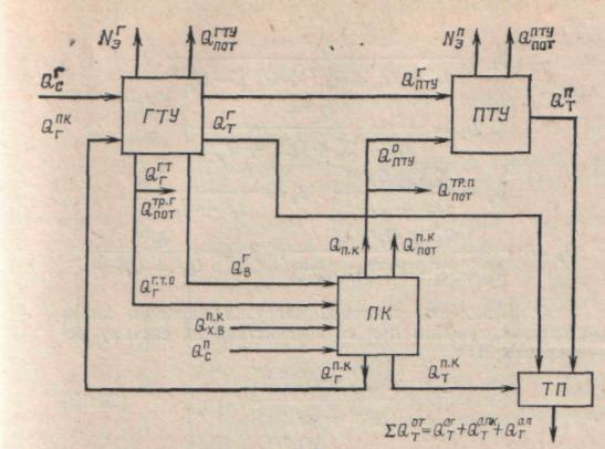
Rice. 9.18. Generalized diagram of heat flows of a combined cycle plant:
 - fuel heat supplied to the PC and gas turbine unit;
  -
electrical power of STU and GTU;
-
electrical power of STU and GTU;  - total heat supply to external consumers;
  - heat costs for external consumers by steam turbine and gas turbine units, steam boiler;
  - heat of air and gases transferred by the gas turbine unit to the steam boiler;
  - heat released by the steam boiler for the PTU;
  - heat supplied to the PC with additional air;
  - heat received by the PTU through the PC;
  - heat gained by the PTU through the GTU;
  - heat released by the steam boiler for the gas turbine unit;
  ,
,
 - heat loss from a steam boiler, gas turbine unit, steam turbine unit during transport in the steam-water and gas-air ducts
Combined-cycle plants are characterized by a complex distribution of fuel heat between the types of energy supplied, which must be taken into account when determining energy indicators.
For a more detailed analysis of the perfection of individual elements of the CCGT equipment and their influence on the installation performance in the generation of electrical and thermal energy, the method outlined below for determining the efficiency was used, based on the generally accepted “physical” method and the proposed generalized scheme of CCGT heat flows (Fig. 9.18). As a result, received in general view expressions for the efficiency of the CCGT and its individual elements, regardless of the specific circuit.
CCGT efficiency for electricity production
Efficiency factor of CCGT unit for thermal energy production
 (20.9)
The following quantities are used in these expressions:
Steam boiler efficiency (direct balance)
Efficiency of heat transport of steam-water and gas-air paths
Efficiency of a steam turbine plant for electricity production
Efficiency of a gas turbine plant for electricity production
Energy coefficients of CCGT units for the production of electrical and thermal energy
Efficiency of heat transport of the gas-air path  Efficiency of steam-water
  and gas-water
  heat exchangers for transferring heat to external consumers are assumed to be constant.
Page 38 of 75
COMBINED COMBINED POWER PLANTS
8.1. The concept of steam-gas energy technologies and the design of the simplest CCGT
Steam-gas are power plants in which the heat from the exhaust gases of a gas turbine is directly or indirectly used to generate electricity in the steam turbine cycle.
In Fig. 8.1 shown circuit diagram the simplest combined cycle plant, the so-called recycling type. The gas turbine exhaust gases enter the waste heat boiler- a counterflow heat exchanger, in which, due to the heat of hot gases, steam of high parameters is generated and directed to a steam turbine.
The recovery boiler is a shaft rectangular section, in which heating surfaces are placed, formed by silvered pipes, into which the working fluid of a steam turbine unit (water or steam) is supplied. In the simplest case, the heating surfaces of a waste heat boiler consist of three elements: economizer3 , evaporator 2 and superheater 1 . The central element is evaporator, consisting of drum 4 (a long cylinder half filled with water), several downpipes 7 and sufficiently tightly installed vertical pipes of the evaporator itself 8 . The evaporator works on the principle natural convection. Evaporation pipes are located in a zone of higher temperatures than downcomers. Therefore, the water heats up in them, partially evaporates and therefore becomes lighter and rises up into the drum. The vacated space is filled with more cold water through drop pipes from the drum. Saturated steam is collected at the top of the drum and directed into the pipes superheater 1 . Steam consumption from the drum 4 compensated by water supply from the economizer 3 . In this case, the incoming water will pass through the evaporation pipes many times before completely evaporating. Therefore, the described waste heat boiler is called boiler with natural circulation.
In the economizer, the incoming feed water is heated almost to the boiling point (10-20 ° C less than the temperature of the saturated steam in the drum, which is completely determined by the pressure in it). From the drum, dry saturated steam enters the superheater, where it is overheated above the saturation temperature. Temperature of the resulting superheated steam t 0 is always, of course, less than the temperature of the gases q Г coming from the gas turbine (usually by 25-30 °C).
Below the diagram of the waste heat boiler in Fig. Figure 8.1 shows the change in temperatures of gases and the working fluid as they move towards each other. The gas temperature gradually decreases from the value q Г at the inlet to the value qух temperature of the exhaust gases. Feed water moving towards it raises its temperature in the economizer to the boiling point (point A). At this temperature (on the verge of boiling) the water enters the evaporator. Water evaporates in it. At the same time, its temperature does not change (the process a - b). At the point b the working fluid is in the form of dry saturated steam. Next, the superheater overheats to a value t 0 .
The steam generated at the outlet of the superheater is directed to the steam turbine, where it expands and does work. From the turbine, the exhaust steam enters the condenser and is condensed using a feed pump. 6 , increasing the pressure of the feed water, is sent back to the waste heat boiler.
Thus, the fundamental difference between a steam power plant (SPU) of a CCGT and conventional PSU Thermal power plant consists only in the fact that the fuel is not burned in the waste heat boiler, and the heat necessary for the operation of the CCGT PSU is taken from the exhaust gases of the GTU. However, it is immediately necessary to note a number of important technical differences between the CCGT PSU and the TPP PSU.
1. The temperature of the gas turbine exhaust gases q Г is almost uniquely determined by the temperature of the gases in front of the gas turbine [see. relation (7.2)] and the perfection of the gas turbine cooling system. In most modern gas turbine plants, as can be seen from Table. 7.2, the flue gas temperature is 530-580 °C (although there are separate gas turbine units with temperatures up to 640 °C). According to operating reliability conditions pipe system economizer when operating on natural gas, feed water temperature t p.v at the inlet to the waste heat boiler should not be less than 60 °C. The temperature of the gases qух leaving the waste heat boiler is always higher than the temperature t p.v. In reality, it is at the level qух » 100 °C and, therefore, the efficiency of the waste heat boiler will be
![]()
where for assessment it is assumed that the gas temperature at the inlet to the waste heat boiler is 555 °C, and the outside air temperature is 15 °C. When operating on gas, a conventional TPP power boiler (see lecture 2) has an efficiency of 94%. Thus, the waste heat boiler in a CCGT plant has an efficiency significantly lower than the efficiency of a thermal power plant boiler.
2. Further, the efficiency of the steam turbine unit of the considered CCGT is significantly lower than the efficiency of the STU of a conventional thermal power plant. This is due not only to the fact that the parameters of the steam generated by the waste heat boiler are lower, but also to the fact that the CCGT steam turbine unit does not have a regeneration system. But in principle she cannot have it, since the increase in temperature t p.v will lead to an even greater decrease in the efficiency of the waste heat boiler.
Nevertheless, with all this, the efficiency of the CCGT turns out to be very high. In order to verify this, let us consider a CCGT of a simple circuit (Fig. 8.2), and during the examination we will accept far from the best economic indicators individual pieces of equipment.
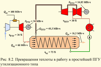
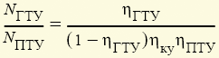
Let a certain amount of gas be burned in the combustion chamber of a gas turbine unit, from which Q ks = 100 MWh of heat. Let us assume that the efficiency of the gas turbine unit is 34%. This means that the GTU will receive E GTU = 34 MWh of electricity. Quantity of heat
enters the waste heat boiler. Let its efficiency be equal to hku = 75%. Then it will go into the chimney from the boiler
and the amount of heat Q vocational school = Q ku - Qхх = 49.5 MWh enters the steam turbine plant for conversion into electricity. Let its efficiency be only h PTU = 0.3; then the electric generator of the steam turbine will produce
electricity. Total CCGT production
electricity and, therefore, the efficiency of the CCGT h STU = E/Q ks = 0.4885, i.e. about 49%.
The above considerations allow us to obtain a simple formula for determining the efficiency of a utilization-type CCGT unit:
This formula immediately explains why CCGT units began to be built only in the last 20 years. Indeed, if we take, for example, a gas turbine unit of the GT-100-ZM type, then its efficiency is h gtu = 28.5%, and the temperature behind the gas turbine is q G = 398 °C. At this gas temperature, steam with a temperature of about 370 °C can be generated in the waste heat boiler, and the efficiency of the steam turbine plant will be approximately 14%. Then, at h ku = 0.75, the efficiency of the CCGT will be
and it would be more expedient to build a conventional SKD steam turbine power unit with greater efficiency. The construction of a CCGT unit became economically justified only after the creation of high-temperature gas turbine units, which not only ensured its high efficiency, but also created the conditions for the implementation of a highly efficient steam turbine cycle. From relation (8.1) one can obtain an almost universal relation between the powers of the gas turbine and steam turbine parts of the CCGT:
those. this ratio is determined only by the efficiency of the CCGT elements. For the example discussed above
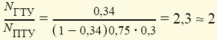
those. The power of a gas turbine is approximately twice that of a steam turbine. It is this ratio that explains why the PGU-450T of the North-Western Thermal Power Plant of St. Petersburg consists of two gas turbine units and one steam turbine with a capacity of approximately 150 MW each.
An idea of the design of a power plant with a CCGT unit is given in Fig. 8.3, which shows a thermal power plant with three power units. Each power unit consists of two adjacent gas turbine units 4
type V94.2 from Siemens, each with its own flue gases high temperature sends it to its waste heat boiler 8
. The steam generated by these boilers is directed to one steam turbine 10
with electric generator 9
and a condenser located in the condensing room under the turbine. Each such power unit has a total capacity of 450 MW (each gas turbine and steam turbine has a capacity of approximately 150 MW). Between the outlet diffuser 5
and waste heat boiler 8
install a bypass (bypass) chimney 12
and gas-tight gate 6
. The gate allows you to cut off the waste heat boiler 8
from the gas turbine gases and direct them through the bypass pipe into the atmosphere. Such a need may arise if there is a problem in the steam turbine part of the power unit (turbine, waste heat boiler, generator, etc.), when it needs to be turned off. In this case, the power of the power unit will be provided only by the gas turbine unit, i.e. the power unit can carry a load of 300 MW (albeit with reduced efficiency). The bypass pipe also helps a lot during startups of the power unit: with the help of a gate, the waste heat boiler is cut off from the gas turbine gases, and the latter are brought to full power in a matter of minutes. Then you can slowly, in accordance with the instructions, put the waste heat boiler and steam turbine into operation.
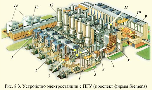
At normal operation the gate, on the contrary, does not allow the hot gases of the gas turbine to pass into the bypass pipe, but directs them to the waste heat boiler.
The gas-tight gate has large area, is a complex technical device, the main requirement for which is high density, since every 1% lost heat through leaks means a decrease in the efficiency of the power unit by approximately 0.3%. Therefore, sometimes they refuse to install a bypass pipe, although this significantly complicates operation.
One deaerator is installed between the waste heat boilers of the power unit, which receives condensate for deaeration from the steam turbine condenser and distributes it to two waste heat boilers.