Connecting an electric boiler 380. Electrical diagrams of boilers. Connecting an electric boiler
Dear visitors!!!
This topic will cover:
- electrical diagrams of boilers;
- possible causes of boiler breakdowns and ways to eliminate them,
options for connecting electric boilers will also be considered for:
- two-wire single-phase network;
- four-wire three-phase network with neutral wire.
For the two connection methods, you need to know that when connecting any electrical equipment, and we are talking about electric boilers that are equated to this category, the connection is made with grounding.
In this topic, the casings of electric boilers are subject to grounding.
Why does this need to be taken into account? - Then, in the event of a breakdown of the conductor phase insulation on the metal parts of the body and a person accidentally touches the body of the electric boiler, the current potential in the human body decreases.
Further, the connection of electric boilers both to a two-wire single-phase network and to a four-wire three-phase network with a neutral wire is carried out with the obligatory connection through an RCD.
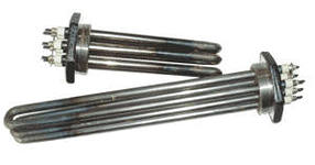
Replacing the heating element
Replacing the heating element and other elements, as well as diagnostics to determine the cause of the malfunction, is carried out in a passive way when the electrical equipment is disconnected from the external alternating voltage source.
This issue cannot be resolved on your own if you are not an electrician and such work is carried out accordingly if you have knowledge of the regulatory documents \electrical safety clearance group\.
So what is the need for these details? — You may ask, if in this or that case there is a malfunction, you can call the electrician directly.
Well, let's put it this way - knowledge of electrical and electrical engineering will not be superfluous for you.
Connecting an electric boiler
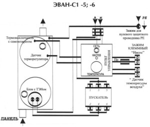
Let's consider connecting the EVAN S1-30 electric boiler to a four-wire, three-phase network with a neutral wire.
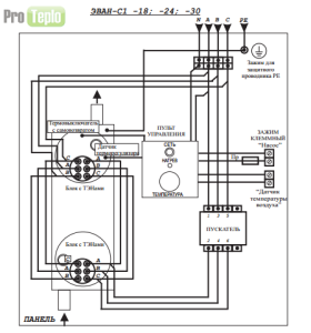
The fifth PE conductor in the diagram in Fig. 1 is grounding and is connected to the body of the EVAN S1-30 electric boiler. Reading the connection diagram:
The electric boiler is equipped with so-called tires, network cable with plug connected to buses \N, A, B, C\. From the buses, three phases \A, B, C\ have branching. One branch of phases \A, B, C\ is connected to the first contacts of the heating elements of two blocks.
The second branch from the same four buses is connected through a starter to the second contacts of the heating elements of two blocks.
Here it should be taken into account that for each individual block with heating elements, each individual heating element is connected to phase wires as follows:
- first heating element \С-А\;
- second heating element \A-B\;
- third heating element \B-C\.
Phase \A\ and neutral wire \N\ from the busbars are connected to the control panel. In its combination, the control panel is connected to voltage \220 V\, the conductors from the control panel are connected:
- with pump;
- with thermostat sensor;
The control panel consists of electronic elements that are not indicated in the diagram.
For electronic elements, diagnostics are outlined in this blog.
After carrying out repairs to replace one or another electrical part:
- block with heating elements;
- self-resetting thermal switch
and other parts included in the electrical circuit, it is necessary, before connecting the electric boiler to an external source of alternating voltage, to check the electrical circuit of the boiler for resistance. Diagnostics of resistance in the electrical circuit of this circuit is carried out either with an ohmmeter or with a multimeter with the appropriate function.
If, as a result of measuring resistance, the device indicates a zero value, in this example you should reconsider the connections you have made. A zero resistance number indicates a short circuit in the electrical circuit.
Let's consider the following electrical circuit for two types of boilers \EPO-7.5\ and \EPO-9.45\. The electrical circuit shown \Fig. 2\ is identical and the difference here is only in the power of electric boilers. Let's follow the connection diagram:
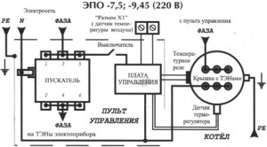
These types of electric boilers are connected to a two-wire, single-phase network. The grounding wire \PE\ is connected to the heating element block and to the body of the electric boiler. The phase wire from the phase bus in this circuit has a branching, one wire with phase potential goes to the control panel and is connected from the control panel to the first contacts of the heating elements,
the second wire with phase potential is supplied through the starter to the electric heating element; also from the starter, the wire with phase potential is connected in series through a switch to the control board. The control board has connections:
- with air temperature sensor;
- with temperature relay of heating elements;
- with thermostat sensor
The neutral wire has a serial connection:
- with starter;
- with control board;
- with the second contacts of heating elements.
The connection diagram for an electric boiler \Fig. 3\ is intended for a two-wire, single-phase network. The power of electric boilers for this scheme is 5-6 kW.
The phase wire from the bus in a serial connection through the starter is connected to the first contact of the heating element. The neutral wire from the bus is connected to the second contact of the heating element. From the phase and zero buses, power is supplied to the control panel. Remote Control
has connections:
- with pump;
- with air temperature sensor;
- with thermostat sensor;
- with thermal switch \with self-reset\.
The PE protective conductor is connected to the body of the electric boiler.
Electric boilers have only minor differences in their electrical circuits.
Current calculation
The RCD is selected taking into account the current strength. We substitute the values using the power formula,
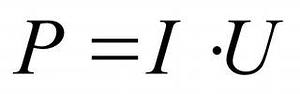
We know two values from the formula - the power of the electric boiler and the voltage. From here we can find the current value.
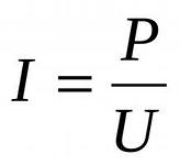
The result of the current strength is known to you, all you have to do is select residual current device based on the calculated current value.
Electric boilers for home heating are a reasonable alternative to solid fuel and gas units. Such heating devices have high efficiency, are silent in operation, and do not require separate room and additional installation permissions.
Depending on the rated power, electric boilers are divided into two types: single-phase (power 1–10 kW) and three-phase (power 12 kW and above). Today we will get acquainted with more powerful devices that require connection to a voltage of 380 volts.
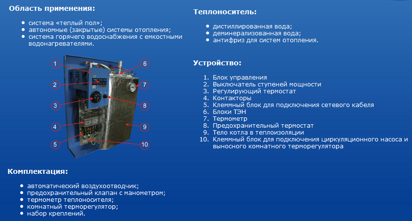
Types of electric boilers
Depending on the method of transferring thermal energy to the coolant, electric boilers divided into three types:
- Tenovye.
- Induction.
- Electrode.
All these heating units are produced in two versions: 220 and 380 volts.
Heating boilers
These electric boilers for home heating are the most popular. The principle of their operation is as follows:
- The tubular element heats the circulating fluid closed system water.
- Circulation ensures fast and uniform heating of the entire system.
- Quantity required heating elements depends on the power of the device and can vary from 1 to 6 heating elements.
 Such boilers are equipped with a reliable automation system that allows you to monitor and regulate the temperature of the coolant. The advantages of heating elements heating units are:
- Simplicity and reliability of design.
- Easy to install.
- Cheap design.
- The ability to use almost any liquid as a coolant.
- Such 380 volt boilers have modern design and fit well into any interior.
Induction boilers
The principle of electromagnetic induction has long been successfully used for heating residential premises. This boiler has the following device:
- A metal core is inserted into a cylindrical body (usually a piece of pipe), on which a coil is wound.
- When voltage is applied to the coil and winding, vortex flows arise, as a result of which the pipe through which the coolant circulates heats up and transfers heat to the water.
- The water circulation must be constant so that the coil and core do not overheat.
 This electric heating system has the following advantages:
- High efficiency, reaching 98%.
- This 380 volt boiler is not susceptible to scale formation.
- Increased safety - no heating elements.
- Small size and low weight provide lightweight and quick installation induction boilers.
Advice! Induction electric boilers can do without a circulation pump. But this does not apply to a large heating system of a two-story house.
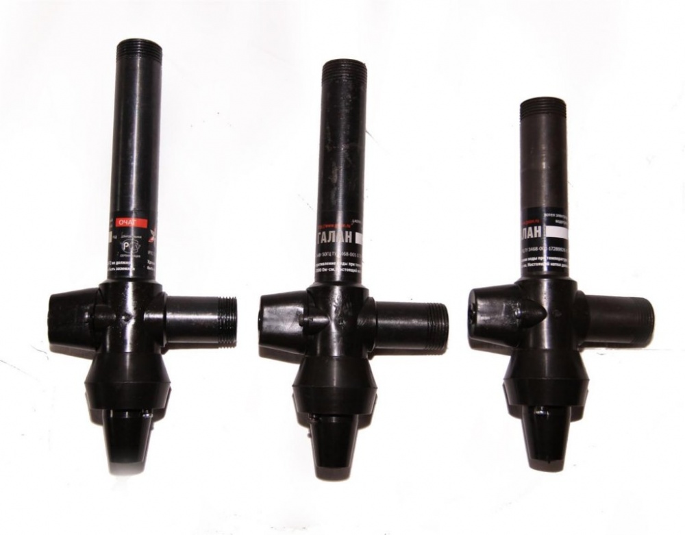
Electrode systems
In its operation, the 380 volt electrode boiler uses specially prepared water. Preparation of the coolant consists of dissolving a certain amount of salts in it to give required density. General principle The operation of electrode heating devices is as follows:
- Down the pipe suitable diameter two electrodes are inserted.
- Due to the potential difference and frequent polarity changes, the ions begin to move chaotically. This way the coolant heats up quickly.
- Due to the rapid heating of the coolant, powerful convection currents are created, allowing you to quickly warm up a large volume without the use of a circulation pump.
 The electrode boiler has obvious advantages, including:
- Small sizes.
- Fast ramp up to rated power.
- Compact and simple design.
- No emergency situation, even if water leaks from the heating system.
Advice! Electrode boilers require a special approach to grounding equipment. Not only the boiler itself is connected to the ground loop, but also the heating system of the house, especially metal radiators.
Manufacturers of electric boilers
Quite a number of products are represented on the domestic market big choice popular brands producing 380 volt electric heating boilers. Among the variety of manufacturers, the most complete the lineup electrical heating equipment The following domestic and foreign companies represent:
- Bosch.
- Danko.
- Ferroli.
- Kospel.
- TermIT.
- Protherm.
All these companies represent electric boilers different principles action, wide power range and all types of connection: single-phase and 380 volts.
Rules for installation and operation of electric boilers
When connecting an electric boiler, you must follow certain rules, which we will now examine in more detail.
Electrical connection
When connecting an electric boiler, it is necessary to correctly calculate the cross-section power cable. The safety of the entire heating system depends on this indicator.
It is worth noting that 380 volt electric boilers are quite powerful, so the cable must be appropriate. To calculate the wire cross-section, a formula is used, according to which no more than 8 A of current should fall per 1 mm2 of cable cross-section.
 According to this formula, in order to connect a 10 kW heating unit to a voltage of 380 volts, it is necessary to make the following calculations: 10000/380/8. The result shows that each conductor of the cable must have a cross-section of at least 3.3 mm.
Advice! When choosing a cable cross-section, fractional values should only be rounded up!
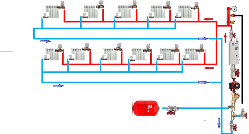
Connection to the heating system
All electric boilers are connected to the heating system according to a similar scheme:
- To connect use plastic pipes or jumpers made of dielectric material.
- The circulation pump must be installed on the return pipe.
- A safety group must be installed on the hot coolant supply pipe (no further than 50 cm from the boiler).
- If the heating system uses a small circuit, then it is necessary to install shut-off valves after it.
- Expansion tank open type installed at the highest point of the pipe system without the use of shut-off devices. Expansion tank closed type installed close to the boiler, up to the shut-off valves.
 During operation of a 380-volt electric boiler, it is necessary to monitor the serviceability of the electrical wiring and prevent coolant leaks.
Advice! When operating electrical heating equipment, special attention should be paid to the serviceability of the grounding conductor. In case of damage, you should immediately turn off the power to the boiler and restore the grounding.
In conclusion, I would like to note that 380 volt electric boilers perform excellently during long-term operation. Due to their greater power, they are less likely to operate at their maximum capacity, which has a positive effect on their service life. Installing such a boiler is an excellent solution to solve the problem of heating a large house.
General rules for installing gas boilers
Depending on the boiler model, they are used different technologies installation, but general rules saved for any gas equipment.
Boiler room in a private house
Rule one.
Heating installations are considered high-risk equipment, so it is recommended to install them in a hotel room (boiler room). In cases with low power domestic boilers They can be installed in any utility room, but when installing one or more boilers with a total power of more than 60 kW, a separate room is required.
Rule two. In most cases, the development of a heating equipment installation plan is entrusted to the design department gas industry, which controls the operation of boilers and allows the supply of gas to it. Therefore, installation is carried out only after receiving the installation diagram and documented gas supply conditions.
Of course, the owner of the installed gas boiler can express his wishes regarding the location of the equipment, but the responsible decision, setting the conditions for the premises and drawing up a plan for connecting the equipment rests with the gas service. This is done based on the fact that there are a number of restrictions on the installation of boilers: minimum room volume and ceiling height, ventilation, lighting, relative arrangement of all elements heating system.
Rule third. Correct installation gas boiler is carried out in accordance with the instructions-description of its passport, and Special attention pays attention to the location of the device relative to the walls and the exhaust gas removal system.
Gases must not be vented onto verandas, under awnings, arches or opening windows to avoid poisoning.
Floor-standing boilers are mounted only on a fireproof floor surface (tiles, concrete, metal) large sizes than the dimensions of the boiler, and wall-mounted units must maintain a distance gap and have a heat shield on the wall.
Rule four. The layout of all gas equipment in the room must ensure minimum distance 0.5 m between them, while easy access to the burners must be maintained for their maintenance and removal for repairs.
Each gas appliance must have a gas pipeline separate from the general main with a shut-off valve, which is made only from metal pipe and him hidden installation not allowed. Where the gas pipeline passes through walls, the pipe is laid with embedded steel sleeves.
Rule five. The connection of the boiler with communications is carried out due to threaded connections, and its connection to the electrical network must have a protection system against voltage surges and short circuits.
Principles of installation of gas boilers
Typical gas boiler connection diagram is divided into five responsible areas according to the specifics and sequence of work.
Boiler installation
The boiler must be installed exactly in the position specified by the manufacturer: distance to the wall, level of its installation from the floor (for wall-mounted ones). Wall-mounted boilers must be mounted on anchor bolts a length of at least 100 mm with a margin of strength to strong wall surfaces to ensure that the load from the weight of the boiler is withstood.
If the wall is not strong enough, double-length anchors are used, up to drilling through the wall and installing studs and wide embedded plates instead of anchors. outside walls.
A correctly installed boiler must take into account the precise preservation of horizontal and vertical level, because deviations may cause air to accumulate in the water circuit, which will reduce thermal efficiency.
Organization of the exhaust gas removal system
Correct installation of the chimney ensures the removal of combustion products, and also, if used coaxial chimney, air flow for high-quality gas combustion. Insufficient draft in the heat exchanger system causes incomplete combustion of the gas, which can cause the accumulation of an explosive mixture.
Depressurization of the chimney or removal of exhaust gases near opening windows and doors can provoke poisoning of the body. Therefore, special attention is paid to the smoke exhaust system, and the tightness is checked periodically during operation.
It is not allowed to install a chimney with a reduced cross-section or with a shortened channel. For boilers with open camera combustion must be ensured constant influx fresh air to the burner area, which requires maintaining sufficient ventilation of the room (natural or forced).
Connecting water communications
At this step, the boiler is connected to the heating and hot water supply system, which is organized only through threaded connections (American ones are recommended) to maintain the possibility of easy shutdown or dismantling of the device.
It is not allowed to reduce the cross-section of the supply pipelines in order to avoid a decrease in efficiency and overheating of the boiler.
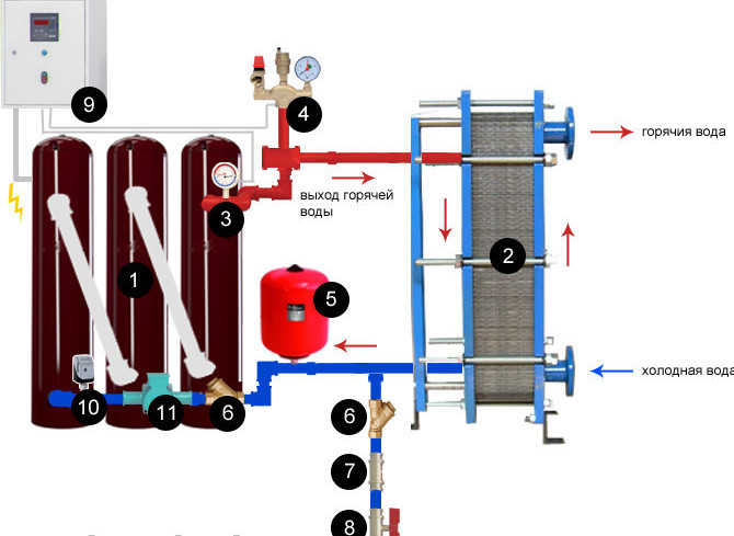
A typical diagram for connecting a gas boiler to a heating system has several basic elements.
Firstly, this expansion tank for coolant, which can be open or closed.
An open-type tank has a connection with the atmospheric environment for timely removal of air from the heating system, and must be installed at the highest point of the heating distribution.
The tank is a closed type and has no connection to the atmosphere and is equipped with a compensation membrane for the liquid expanding when heated. Such a tank can be mounted in any convenient place in conjunction with a valve that releases excess fluid pressure and accumulated air, located at the highest point of the system.
Installation of shut-off valves on an open-type expansion tank is not permissible, because heating the coolant causes it to expand and increase pressure in the system, which can destroy the boiler heat exchanger .
The next element is coarse and fine water purification filters, and their installation is recommended both heating circuit, and on the hot water supply circuit, since during the circulation of water through the pipes, debris in the form of sand and loose scale deposits accumulates. Filters are installed on the inlet pipes of boilers, which reduces clogging and increases the efficiency of heaters.
Disassembled heating system filter
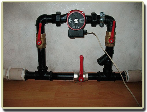
It is impossible not to say about circulation pumps, which are not always included in the design of boilers. They allow you to increase the efficiency of heating and hot water supply.
Pumps are installed in the gap between filters and heaters, while installing a pump for water supply is only relevant when the pressure in the pipeline is low, because otherwise, the automatic boiler-column system for gas supply will not operate.
AND finishing touch— communication and distribution block with shut-off valves. A pipeline decoupling system with a manifold for several boilers and contour heating outlets allows you to optimally regulate the coolant circulation in different areas of the house.
The distribution block must have a connection to the water supply to replenish the heating system, and is equipped with an outlet to the street or to the sewer for draining the coolant in emergency cases.
Connecting boilers to the electrical network
Includes the provision of high-quality electrical wiring with the mandatory installation of an RCD (residual current device), which will ensure that electricity is cut off in the event of a short circuit or current overload.
Due to the sensitivity of the electronic units of many gas boilers to voltage surges, it is recommended to install voltage normalizers or, in extreme cases, power cut-off units during power surges.
In cases where there are periodic power outages, it is strongly recommended to connect the system uninterruptible power supply(to avoid freezing of the heating system) in parallel to the electrical network, which may include batteries with a converter or a generator.
Gas supply and connection to boilers
This step is carried out only if there is permitting documentation from gas service and when performing all the above work. Gas supply pipelines must be carried out only with external wiring from steel pipe, and the tightness of all connections must be impeccable. Each gas appliance must have its own tap, which is located at eye level, i.e. 1.2-1.5 m from floor level.
Gas pipeline connection
The gas main must have a filter that traps mechanical debris and partially condensate. New communications before connecting gas automation boilers must be thoroughly ventilated, because even small debris picked up by gas can damage the automation or clog its calibrated channels of small cross-section.