Diagram of the upper wiring of the heating system. Upper and lower heating system wiring
The two-pipe heating system for a private home is much easier and cheaper to install, and the two-pipe heating system for a private home does not lose its popularity.
This becomes possible only thanks to the few, but unique advantages that such structures have.
Two highways - what are they?
The biggest distinctive feature such schemes is the presence of two separate highways. The first is designed to deliver water to all heating elements, that is, radiators, and the second serves to collect cooled water and deliver it to a heating element, for example, a gas boiler.
If in a single-pipe design with forced or natural circulation The coolant partially cools down until it reaches each individual radiator; in the case of a two-pipe system, this process is hardly noticeable.
Scheme two-pipe system heating has the following positive qualities:
- Installation of such systems does not require pipeline elements with large diameter, since there will be practically no obstacles on the path of the coolant, which cannot be said about single pipe heating. Since thinner pipes cost less, the overall project cost will be less. We can also add here that smaller pipes will require smaller valves, fasteners and other shaped elements, which, naturally, also cost less;
- It is possible to install thermostats near each heating radiator, which significantly increases the operating comfort of such heating;
- It must also be said that thinner pipes, fasteners and valves are not so “conspicuous”, so they do not spoil the interior.
As for the disadvantages, we can note one and probably the most relevant one - the cost. In fact, it is not large, but in comparison with a single-pipe system, it is much larger. However, having assessed all the pros and cons, for a private residential building, especially if we are talking about a multi-storey dwelling, the choice leans towards a two-line design.
Classification
So, it should be noted right away that gravity flow schemes with two highways can rarely be found. In fact, they should not exist at all, since they are ineffective. If you are destined to meet similar ones anywhere, then only in very old houses.
It must also be said that today all gas and electric boilers already have a pump in their design, so these designs are called with forced circulation.
Among other things, these types of heating can be:
- Horizontal;
- Vertical.
Both of them can be done with your own hands.
The division into these two categories is carried out according to the location of the pipeline. It must be said right away that there are no differences in the design itself, and the list of constituent elements is as follows:
- Riser;
- Heating elements, that is, radiators;
- Shut-off valves on each of the radiators;
- Air bleed valve;
- Some elements of control valves;
- Direct line;
- Return line;
- The heating element, that is, the boiler.
Of course, the entire heating system with forced circulation, both with bottom and top wiring, may include other elements, but the main ones are listed here.
So that's it vertical diagrams have a characteristic structure in which all elements are connected to the riser.
Advice! A two-pipe building or a building with a large number of floors should be built precisely according to this principle, since such a design does not allow air cavities to form inside the pipeline.
Scheme with horizontal wiring suitable for houses and buildings that have one floor and a fairly large heating area. In this case, the connection will be much simpler and the cost will be lower.
Bottom and top wiring
Among other things, the division is also carried out according to the method of laying the pipeline, that is, according to the method of installing the wiring. There are different schemes:
- With bottom wiring;
- With top wiring.
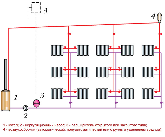
Upper wiring
The most important difference from the others is that this type It has expansion tank, which is installed at the highest point. In addition, this expansion tank must be located above all other elements.
![]()
Structurally, such a system should contain the following elements:
- Heating boiler;
- Circulation pump;
- Expansion tank;
- Air collector, which can be manual, automatic or semi-automatic.
Advice! This type of structure should be assembled with your own hands only in a pre-insulated attic, or the expansion tank itself should be additionally insulated.
It should also be noted that such a scheme is not suitable for a one-story building with a flat roof.
Bottom wiring
All systems with bottom wiring have the peculiarity that the supply line is usually located in basement. Often the supply and return lines are located on the floor.
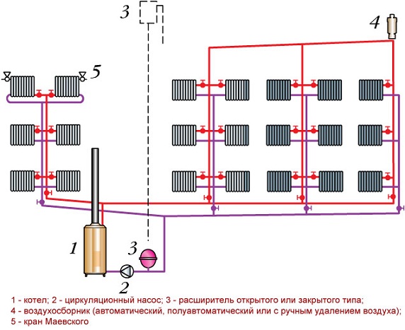
Structurally, this scheme will include the following elements:
- Heating boiler;
- Circulation pump;
- Expansion tank;
- Air collector;
- Mayevsky crane.
It must be said that regardless of where the supply pipes are located, the boiler must be located below the level of the return line.
Direction of coolant movement
Along with the above classification, all two-line heating systems with forced circulation are divided into the following types:
- Straight-through;
- Dead-end.
Direct-flow systems are characterized by the fact that both in the direct line and in the return line, the liquid moves in the same direction.
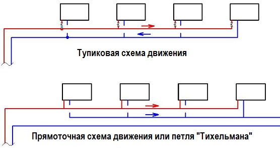
Dead-end ones have different directions of coolant movement in different mains.
It must be said that all such schemes, as noted earlier, in the vast majority of cases today are equipped with a circulation pump. But in principle, the existence of circuits with lower wiring with natural movement of the coolant is possible. When constructing such structures, it is important to remember that minimum slope pipeline should be 1 percent of total length.
Basic rules of hydraulic calculation
Hydraulic calculation is necessary in order to correctly calculate the pressure loss in the system, determine the power of the heating boiler, determine the minimum required pipe diameter, the number of radiators and much more.
However, it is extremely difficult to make such a calculation without the appropriate knowledge, so we will consider only some of the rules for its implementation.
Hydraulic calculations are performed only according to a pre-designed diagram.
The main object will, as a rule, be the most loaded ring, which is divided into several separate sections - hydraulic calculations are carried out on each of them.

It must be said that, depending on the desired value, the hydraulic calculation can be carried out in different ways, that is, it can have several types.
The most relevant for private construction are the following:
- Hydraulic calculation for finding specific linear pressure losses;
- By finding the system resistance.
The first calculation shows the possible pressure loss in the system due to its imperfection, that is, the numerous turns of the pipeline, for example. The second shows how much resistance the coolant flow has from one or another obstacle.
No matter how different these calculations may seem, they have the same goal - to determine how various twists, roughnesses and other obstacles will affect the thermometer reading.
The top layout of the heating system means that the supply pipeline is located in the attic or under the ceiling. From the supply pipe, risers are laid down with pipes attached to them, which in turn are connected to heating devices. The return line is laid on the floor or in the basement. Such a system of polypropylene pipes is an undisputed option for arranging a heating system without a circulation pump.
In other heating schemes circulation pump must be present without fail. In addition, when installing a heating system with wiring from above in the attic, it is necessary to install an expansion tank to protect the system from pressure changes, and an air vent.
The lower distribution differs in that the direct pipeline runs parallel to the return line along the floor of the first or ground floor or in the basement along the ceiling. Such wiring using polypropylene heating pipes used to organize the supply of coolant to each riser.
The heating system can be one- or two-pipe, if you look at the number of pipelines leaving the main line. When installing a one-pipe system, you need to know that in such a scheme the pipe is alternately connected to each device in the system. Moreover, from one radiator to another, the further along the system, the coolant loses temperature. This system it is applied for big houses, where residential premises are first connected to heating, and then utility or utility rooms. 
The two-pipe system is designed so that the hot flow and the already exhausted flow go through different main pipelines - forward and reverse. In this case, coolant with the same temperature will be delivered to each radiator. The great advantage of a two-pipe heating system with radiators connected polypropylene pipes The fact is that in the event of an emergency, you can turn off the problematic riser without depriving the entire house of heating.
Heating distribution in horizontal and vertical types
The vertical type of wiring is usually done in high-rise buildings, where the coolant must pass through risers from floor to floor. With this system, it is possible to repair a separate riser without disconnecting the others. 
Horizontal distribution is the main riser and floor branching in one- and two-pipe versions. This scheme more modern and used in new apartment buildings, where each apartment has its own wiring.
In turn, the horizontal type is perimeter and radial.
Perimeter heating system
This system is connected to the central riser and the coolant moves sequentially through all radiator batteries located along the perimeter of the apartment or floor. This scheme has its disadvantages:
- when repairing one radiator, it is necessary to disconnect the entire perimeter;
- It is difficult to drain the coolant, since the wiring is located at the same level horizontally.
The advantages of the perimeter system include the ability hidden installation lines in the floor. 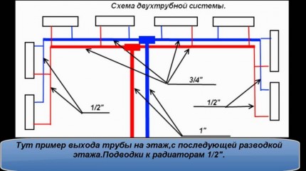
Collector-beam heating scheme
Similar to the previous one, the system is connected to the central riser. The main difference between this scheme is the distribution of pipes in individual rooms, like rays to each radiator. one system pipelines are formed in the collector near the riser. The disadvantages of this system are similar to the perimeter system, and the advantages are the ability to turn off one heating branch without making others inoperable.
Choosing the optimal heating system, one should take into account the climatic conditions of the place of residence, the number of floors of the room, the load on individual heating devices, and the possibility of emergency shutdown.
Unlike single pipe system, where the common pipe conducts hot water through all radiators, and brings it back, a two-pipe heating system with an upper distribution, as well as a lower one, has separate circuits for supplying hot coolant and for discharging waste water back to the boiler. The advantage of this scheme is that the coolant will not gradually lose heat, moving from battery to battery, and the room will be heated more evenly. The only downsides are the higher cost and labor-intensive installation.
The design of a forced circulation heating system can be different, depending on the characteristics of a particular building.
Vertical and horizontal schemes
A double-circuit heating system with forced circulation can differ in the direction of installation of risers: vertical or horizontal. The two-pipe scheme of the first type has the following advantages:
- Allows you to connect every floor two-story house to the riser separately;
- Vertical installation prevents the formation air jams.
The disadvantages of vertical wiring are limited only by the fact that installing a water heating system with your own hands has an increased cost.
The horizontal heating system of a private house is used more often in buildings with one floor. Radiators are connected to such a system in two ways:
- Beam or collector;
- Consistent.
At collector circuit connections, each radiator receives coolant separately. The first type of system has everything heating devices have a common pair heating circuits, which are combined by a collector box. The advantages of the first option are that there is no need to adjust the system with your own hands and control the flow of shut-off valves; the temperature of the radiators will be the same throughout the entire system. However, the price of materials is higher due to the higher pipe consumption. The sequential connection diagram is simpler and more practical, allowing you to easily adjust the temperature of the coolant.
Important! Installation beam system justified only in one-story house. For a two-story house and more floors, it is better to choose a sequential scheme.
Upper and lower wiring
A two-pipe system with top wiring is always vertical, and the radiators in it are connected in parallel. In such a heating system for a two-story house, there must be an expansion tank mounted at the top point of the supply circuit. Pipes of both circuits should be installed with a slight deviation from the horizontal along the flow of water. The system is fed with water through the pipes of the outlet circuit. Cold water mixes with the removed coolant, increasing its density and increasing the circulation pressure in the heating system.
The operating diagram of a forced circulation system is as follows: the pump drives the heated coolant into the attic of a two-story house, from where the water descends into the lower rooms along the supply circuit, ending up in the radiators. Having given up its heat to them, the water flows back into the boiler through the return pipe, the pipes of which are located below the level of installation of the batteries.
A two-pipe heating system with bottom wiring differs from the previous type in that the supply circuit is laid with your own hands next to the discharge pipes, and water is supplied from below. Bottom wiring is rarely used due to the fact that it has significant disadvantages. In a system with bottom wiring, the formation of air jams is inevitable, which makes it necessary to supply all final radiators with Mayevsky taps, through which the air must be bleed every week.
Dead-end and associated systems
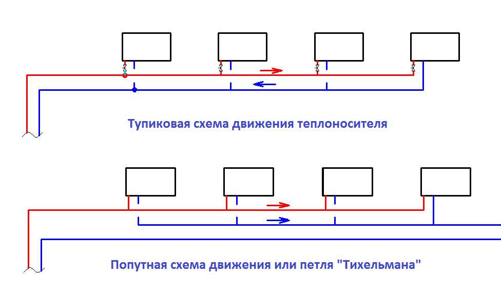 Heating systems with forced circulation may differ in the direction of coolant flow. According to this feature, the system can be dead-end or straightforward:
- At passing traffic the direction of the supply and return flows coincides;
- Dead-end coolant circulation involves multidirectional water flow.
A system with bottom or top wiring can also be open or closed type. Their difference is that open system is flow-through, is supplied with hot coolant centrally or has a leaky circuit. IN closed system with forced circulation, the coolant is heated in a closed circuit. The first two-pipe system scheme is usually used in multi-apartment and multi-storey buildings, and the second is more suitable for a one- or two-story private house.
A double-circuit heating system with lower or upper wiring consists of the following elements:
- Heating boiler;
- Radiators;
- Pipe and pipeline filter;
- Expansion tank;
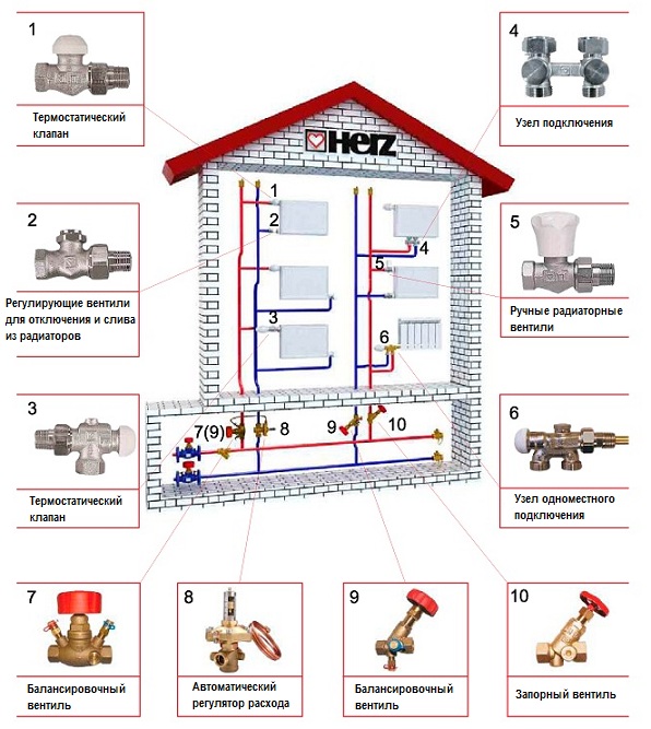
- Balancing fittings – valves, taps, flaps;
- Pump in the case of forced circulation;
- Safety groups and pressure gauges.
Hydraulic calculation
H2_2Hydraulic calculations are carried out using many techniques, the most popular of which are:
- Calculation based on specific pressure loss indicators, which involves obtaining information about temperature fluctuations in all elements of the heating system and the exact coolant flow rate;
- Calculation of a two-pipe heating system based on the resistance and conductivity of the circuits.
As a result, hydraulic calculation provides information on the exact temperature characteristics of the heating system and water flow in all areas, which allows you to create a picture of heat distribution throughout the room and plan optimal scheme heating a two-story house.
Important! The collector part of the system must be calculated separately.
DIY installation and balancing
 Double-circuit heating with forced circulation for a two-story house must be installed and adjusted in compliance with the following rules:
- The inlet circuit must be located above the outlet;
- The slope of the pipes towards the last radiator is from 0.5 to 1% of the entire length;
- The lower and upper contours should run symmetrically and parallel to each other;
- All elements of the system are connected by equipping them with shut-off valves;
- The supply circuit must be covered with insulation to prevent heat loss;
- The contours are fastened in increments of 120 cm.
Installation of a heating system for a two-story house includes the installation of an expansion tank, a heating boiler, radiators and piping. When performing the installation yourself, you should consider:
- The supply circuit departs from the boiler and is first connected to expansion tank, then the pipe goes to the radiators;
- In a system with forced circulation, the pump is installed as close as possible to the starting point, that is, at the outlet of the boiler room;
- The return circuit is mounted parallel to the supply pipeline, connected to all batteries and supplied to the boiler;
- Radiators should be installed in compliance with optimal distances - about 10 cm from the floor and a few centimeters from the walls;
- Next to the radiators, shut-off valves and elements are installed, with the help of which the system is balanced.
If used collector system with lower wiring, all circuits are additionally connected by a collector pipe. Its diameter must be no less than the sum of the diameters of the pipes included in it.
Balancing includes a test run of the system, removal of air through Mayevsky valves, checking pressure and temperature. The optimal operating mode is adjusted based on temperature using taps or balancing valves or by coolant flow, using electronic flow meters, the connection of which must occur through balancing valves. You can more accurately regulate the temperature with your own hands using thermostats.