Calculation of the capacitance of the ballast capacitor for a transformerless power supply. Capacitor power Powering high-power LEDs through a capacitor
At the very beginning of the topic, regarding the selection of a quenching capacitor, we will consider a circuit consisting of a resistor and a capacitor connected in series to the network. The total resistance of such a circuit will be equal to:
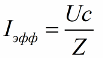
The effective current value, accordingly, is found according to Ohm’s law, the network voltage divided by the total resistance of the circuit:
As a result, for the load current and input and output voltages we obtain the following relationship:
![]()
And if the output voltage is low enough, then we have the right to assume approximately equal to:
![]()
However, let's consider from a practical point of view the issue of selecting a quenching capacitor for connecting to an alternating current network a load designed for a voltage lower than the standard mains voltage.
Let's say we have a 100 W incandescent lamp rated at 36 volts, and for some incredible reason we need to power it from a 220 volt household network. The lamp requires an effective current equal to:

Then the capacity of the required quenching capacitor will be equal to:
Having such a lamp, we gain hope of getting a normal glow from the lamp; we hope that at least it will not burn out. This approach, based on the effective value of the current, is acceptable for resistive loads such as a lamp or heater.

But what to do if the load is nonlinear and is switched on through? Let's say you need to charge a lead-acid battery. What then? Then the charging current for the battery will be pulsating, and its value will be less than the effective value:
Sometimes a radio amateur may find it useful to have a power source in which a quenching capacitor is connected in series with a diode bridge, at the output of which there is, in turn, a filter capacitor of significant capacity, to which a DC load is connected. It turns out a kind of transformerless power source with a capacitor instead of a step-down transformer:
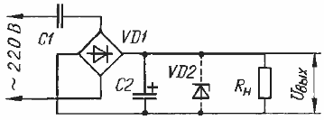
Here the load as a whole will be nonlinear, and the current will no longer be sinusoidal, and calculations will need to be carried out somewhat differently. The fact is that a smoothing capacitor with a diode bridge and a load will outwardly manifest itself as a symmetrical zener diode, because the ripple with a significant filter capacitance will become negligible.
When the voltage on the capacitor is less than a certain value, the bridge will be closed, and if it is higher, the current will flow, but the voltage at the bridge output will not increase. Let's look at the process in more detail with graphs:

At time t1, the network voltage has reached amplitude, capacitor C1 is also charged at this moment to the maximum possible value minus the voltage drop across the bridge, which will be approximately equal to the output voltage. The current through capacitor C1 is zero at this moment. Then the voltage in the network began to decrease, the voltage on the bridge also, but on capacitor C1 it does not change yet, and the current through capacitor C1 is still zero.
Next, the voltage on the bridge changes sign, tending to decrease to minus Uin, and at that moment current flows through the capacitor C1 and through the diode bridge. Further, the voltage at the bridge output does not change, and the current in the series circuit depends on the rate of change of the supply voltage, as if only capacitor C1 was connected to the network.
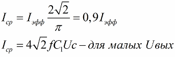
When the network sinusoid reaches the opposite amplitude, the current through C1 again becomes equal to zero and the process goes in a circle, repeating every half period. Obviously, the current flows through the diode bridge only in the interval between t2 and t3, and the value of the average current can be calculated by determining the area of the patch under the sine wave, which will be equal to:
If the output voltage of the circuit is small enough, then this formula approaches the one obtained earlier. If the output current is set equal to zero, we get:
![]()
That is, if the load breaks, the output voltage will become equal to the amplitude of the mains voltage!!! This means that such components should be used in the circuit so that each of them can withstand the amplitude of the supply voltage.
By the way, when the load current decreases by 10%, the expression in parentheses will decrease by 10%, that is, the output voltage will increase by about 30 volts, if we are initially dealing with, say, 220 volts at the input and 10 volts at the output. Thus, the use of a zener diode in parallel with the load is strictly necessary!!!
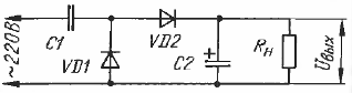
What if the rectifier is half-wave? Then the current must be calculated using the following formula:
At small values of the output voltage, the load current will become half that of full bridge rectification. And the output voltage without load will be twice as high, since here we are dealing with a voltage doubler.
So, a power source with a quenching capacitor is calculated in the following order:
The first step is to choose what the output voltage will be.
Then the maximum and minimum load currents are determined.
If the load current is assumed to be variable, a zener diode in parallel with the load is required!
Finally, the capacitance of the quenching capacitor is calculated.
For a circuit with full-wave rectification, for a network frequency of 50 Hz, the capacitance is found using the following formula:

The result obtained from the formula is rounded towards the capacity of a larger nominal value (preferably no more than 10%).
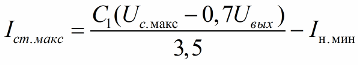
The next step is to find the stabilization current of the zener diode for the maximum supply voltage and minimum current consumption:
For a half-wave rectification circuit, the quenching capacitor and the maximum zener diode current are calculated using the following formulas:

When choosing a quenching capacitor, it is better to focus on film and metal-paper capacitors. Film capacitors of small capacity - up to 2.2 microfarads for an operating voltage of 250 volts work well in these circuits when powered from a 220 volt network. If you need a large capacitance (more than 10 microfarads), it is better to choose a capacitor with an operating voltage of 500 volts or more.
Andrey Povny
Some radio amateurs, when designing network power supplies, use capacitors instead of step-down transformers. ballast, dampening excess voltage (Fig. 1).
A non-polar capacitor included in an AC circuit behaves like a resistance, but, unlike a resistor, does not dissipate the absorbed power in the form of heat, which makes it possible to design a compact power supply that is lightweight and cheap. The capacitance of a capacitor at frequency f is described by the expression:
![]()
The capacitance value of the ballast capacitor Cb is determined with sufficient accuracy using the formula:

where U c is the network voltage, V;
I N - load current, A;
U H is the load voltage, V. If U H is in the range from 10 to 20 V, then the following expression is quite acceptable for calculation:

Substituting the values of U c = 220 V and U H = 15 V, at I n = 0.5 A we obtain the values Sb = 7.28 μF (1) and Sb = 7.27 μF (2). Both expressions give a pretty good match, especially considering that capacitance is usually rounded up to the nearest higher value. It is better to select capacitors from the K73-17 series with an operating voltage of at least 300 V.
When using this circuit, you must always remember that it is galvanically connected to the mains and you risk getting an electric shock at mains voltage potential. In addition, measuring equipment or any additional devices should be connected very carefully to a device with a transformerless power supply, otherwise you may end up with fireworks that are not at all festive.
To power even low-power devices, it is better to use step-down transformers. If the voltage of its secondary winding does not correspond to the required one (exceeds), then it is quite safe to use a quenching capacitor in the circuit of the primary winding of the transformer to reduce the voltage or to connect a transformer with a low-voltage primary winding to the network (Fig. 2). The ballast capacitor in this case is selected based on the calculation so that at maximum load current the output voltage of the transformer corresponds to the specified one.
Literature
1. Biryukov S.A. Devices on microchips. - M., 2000.
I. SEMENOV,
Dubna, Moscow region.
| Circuit voltage, Ua |
| Circuit frequency, f |
| Capacity of the step-down capacitor, C |
| Load voltage, Ub |
| Current flowing through the load, I |
| Load power, P |
If you have ever had the task of reducing the voltage to any level, for example from 220 Volts to 12V, then this article is for you.
There are many ways to do this using available materials. In our case, we will use one part - a container.
In principle, we can use ordinary resistance, but in this case, we will have the problem of overheating of this part, and then a fire is not far away.
In the case when a capacitance is used as a reducing element, the situation is different.
A capacitance connected to an alternating current circuit has (ideally) only reactance, the value of which is found according to the well-known formula.
In addition, in our circuit we include some kind of load (light bulb, drill, washing machine), which also has some kind of resistance R
Thus, the total resistance of the circuit will be as
Our circuit is in series, and therefore the total voltage of the circuit is the sum of the voltages on the capacitor and on the load
Using Ohm's law, we calculate the current flowing in this circuit.
As you can see, knowing the parameters of the circuit, it is easy to calculate the missing values.
And remembering how power is calculated, it is easy to calculate the parameters of the capacitor based on the power consumption of the load.
Keep in mind that in such a circuit you cannot use polarized capacitors, that is, those that are included in the electronic circuit in strict accordance with the indicated polarity.
In addition, it is necessary to take into account the network frequency f. And if in Russia we have a frequency of 50Hz, then for example in America the frequency is 60Hz. This also affects the final calculations.
Calculation examples
It is necessary to power a 36W light bulb designed for a voltage of 12V. What capacity of the step-down capacitor is needed here?
If we are talking about electrical networks in Russia, then the input voltage is 220 Volts, frequency 50 Hz.
The current passing through the light bulb is 3 Amperes (36 divided by 12). Then the capacity according to the above formula will be equal to:
| The obtained parameters of the step-down capacitor |
Hi all! I surfed the site a lot, and especially in my thread, and found a lot of interesting things. In general, in this article I want to collect all kinds of amateur radio calculators so that people don’t search too hard when the need arises for calculations and circuit design.
1. Inductance Calculator- . We thank you for the presented program. crab
2. Universal radio amateur calculator- . Thanks again crab

3. Tesla coil calculation program- . Thanks again crab

4. GDT to SSTC Calculator- . Provided by [)eNiS

5. Program for calculating the circuit of a lamp PA- . Thanks for the information crab

6. Transistor identification program by color- . Acknowledgments crab

7. Calculator for calculating power supplies with a quenching capacitor- . Thanks to forum visitors

8. Pulse transformer calculation programs- . Thank you GOVERNOR. Note - the author of ExcellentIT v.3.5.0.0 and Lite-CalcIT v.1.7.0.0 is Vladimir Denisenko from Pskov, the author of Transformer v.3.0.0.3 and Transformer v.4.0.0.0 is Evgeniy Moskatov from Taganrog.

9. Program for calculating single-phase, three-phase and autotransformers- . Thank you reanimaster
10. Calculation of inductance, frequency, resistance, power transformer, color marking - . Thank you bars59

11. Programs for various amateur radio crews and not only - and . Thank you reanimaster

12. Radio Amateur Assistant- amateur radio calculator - . Topic on . Thank you Antracen, i.e. to me:)

13. Program for calculating DC-DC converter- . Acknowledgments crab
Sometimes in electrical engineering power supplies that do not contain a transformer are used. In this case, the task of reducing the input voltage arises. For example, reducing the alternating voltage of the network (220 V) at a frequency of 50 hertz to the required voltage value. An alternative to a transformer is a capacitor, which is connected in series with the voltage source and load (for more information on the use of capacitors, see section "). Such a capacitor is called a quenching capacitor.
To calculate a quenching capacitor means to find the capacitance of a capacitor that, when connected to the circuit as described above, will reduce the input voltage to the required voltage at the load. Now we get the formula for calculating the capacity of the quenching capacitor. A capacitor operating in an alternating current circuit has a capacitance (), which is related to the frequency of the alternating current and its own capacitance () (and), more precisely:

According to the condition, we included a resistance (resistive load()) and a capacitor in the alternating current circuit. The total resistance of this system () can be calculated as:
Since the connection is serial, using , we write:

where is the voltage drop across the load (device supply voltage); - mains voltage, - voltage drop across the capacitor. Using the above formulas, we have:
If the load is small, then using a capacitor, including it in series in the circuit, is the easiest way to reduce the mains voltage. If the voltage at the power output is less than 10-20 volts, then the capacity of the quenching capacitor is calculated using the approximate formula:
