Self-attachment of ridge beams for the roof of a house. Installation of a rafter system for a gable roof. Is a purlin needed on the roof?
Building a house from the foundation to the top - amazing event! Especially if you do some of the work with your own hands, you live and breathe the future nest. And you know that no matter how much fatigue accumulates towards the finishing work, everything still needs to be done competently and thoroughly. Especially when it comes to the roof, where any mistakes can lead to expensive and unpleasant repairs.
Therefore, in order for the “umbrella” of your dream home to serve properly, do everything correctly structural units, especially the splicing of rafters in the ridge area - this is the highest point! And we will help you understand the types of connections and important technological nuances.
Useful video instructions:
What is a roof ridge?
So, first, let's understand the concepts a little.
So, a purlin is an additional beam that is placed parallel to the roof ridge and the mauerlat. Speaking in simple language, this is the same Mauerlat, only raised in level. And as a result, the ridge should be located at a certain distance from the purlin - depending on what angle of the roof was chosen.
A ridge is a horizontal roof element that connects both roof slopes at the top point.
And the main task connecting elements in the ridge - creating reliable rigidity and strength of the entire roof structure. This is what we will talk about now.
Types of rafter splicing in the ridge
There are three ways to do this:
Method number 1. overlap
This method differs from all previous ones in that here the rafters are connected by side planes and tightened with a pin or bolt. Quite a popular technology today.
If the house is wooden, then the top log or timber will be suitable as a support for this method, but you will have to put a mauerlat on the blocks.
The most popular type of fastening is splicing rafters into half a tree:
Overlapping ridge rafters are most often connected using nails. Usually these are the roofs of gazebos, sheds, bathhouses and garages - not here special requirements to the strength of the rafter system.
Method number 2. Butt connection
To do this you need:
- Cut the edge of the rafter at an angle so that this angle is equal to angle roof slope.
- Support the rafters.
- Apply fastener.
It is much easier to make such trims using a template - just make it in advance. So all the planes will fit tightly against each other.
If you are fastening rafters with nails, use at least two of them. Hammer each of the nails into the upper cavity of the rafters at an angle so that the nail goes into the cut of the second rafter being joined. Additionally, strengthen the splice of the rafters in the ridge with a metal plate or wooden overlay.

Or partially end-to-end:

The essence of this design is that the edges of the two rafters are adjusted so precisely that they evenly distribute the load placed on them with each other. But it will not be enough to secure this connection with one nail - you also need metal or wooden attachments. Take a board 30 mm thick, secure it to one (preferably two) sides of the assembly and nail it.
Method No. 3. Connection to timber
In this method we will attach the rafters directly to the ridge beam. This design is good in that the beam can be provided with central supports, and each rafter can be fastened separately and at a convenient time. This method is irreplaceable if you don’t have time to make a template.
A connection to a ridge beam is recommended in cases where the roof is wide enough - wider than 4.5 meters. This design is quite reliable, but sometimes it requires the installation of additional supports underneath, which reduces the functionality of the attic significantly. After all, there are now beams in the middle of the room! For small ones attic roofs This, of course, is not a problem, but in the attic it will have to be used as an element of the interior. But no template is needed for this design, and small discrepancies are not scary.

Variation:


You can, of course, use a metal fixing plate - but this is only a connection, not a tightening. The essence of the tightening is that it is located lower and takes on part of the load.
This is a combined splicing of rafters, because it is performed end-to-end, exactly the same as when focusing on the mauerlat.
How to splice? Selection of fasteners
The rafter legs form the contour of the roof and transfer the point load from the roof to the mauerlat, and the mauerlat, in turn, evenly distributes it to the load-bearing walls.
The following elements have long been used to fasten rafters:
- Overlays.
- Bars.
- Wooden pins.
- Wedges.
- Nageli.
- Metal staples.
But the modern market offers more functional fasteners that make splicing rafters in the ridge area much easier and more reliable. At any angle, the desired rigidity and strength are obtained. This:
- Nail and perforated plates.
- Self-tapping screws.
- Bolts and screws.
- And much more.
But the choice of one or another fastening element no longer depends on how much it costs and how strong it turns out to be, but on what the load is on a particular ridge unit and what it requires.
So, here’s how, for example, rafters in a ridge are spliced with self-tapping screws:

And here it is with nail and perforated plates:

But in order to use these plates, you will have to work with the press:

And now - from simple to complex.
Splicing rafters at the ridge of a gable roof
When resting on the ridge girder of a gable roof, the rafter legs can either rest against each other with their beveled ends or be apart.
- If the rafters rest against each other with their ends, in other words, end-to-end, then their ends need to be connected with overlays on nails or bolts.
- If the ends of the rafter legs in the ridge assembly are located apart, then they are connected with corner brackets and bolts.
- If the rafter legs rest on two purlins at once, then the ends of the legs also rest on each other. Naturally, a certain thrust arises, the tension of which is relieved with the help of horizontal crossbars.
- If there is no purlin at all, then the junction of the rafter legs in the ridge unit is made by placing the beveled ends of the legs against each other. Additionally, such joints need to be secured with paired overlays, which are nailed to the legs or connected with bolts.
- To secure the rafter leg with the crossbar, the joint is made using wooden side plates. They are nailed directly to the crossbar or bolted - it all depends on the cross-sections of the materials used. Next, a block is placed under the crossbar to absorb transverse forces.
- But rafter legs made of logs with a crossbar are already attached without overlays. Only at the end of the crossbar itself is a notch made ½ from the section of the truss. To ensure that the system ultimately turns out to be stable, the rafter legs are reinforced in the transverse direction with struts and crossbars. Especially when it comes to the span width between external load-bearing walls of 8 meters or more.
- If strong winds are not uncommon in the area, it is extremely important to protect the roof ridge from possible displacement. And for this purpose, the ends of the rafters are additionally connected to the ridge girder with corner brackets. Plus, the rafter legs and the masonry of the house must be secured with wire.
- If you are splicing a rafter system from logs in a ridge, round timber, then expect it to be quite heavy.
Note that when there are significant loads on the rafter system, it is not recommended to make a tie-in in the rafter leg at all - only use intermediate gussets.

Here are more details:


If rafter diagram are inclined, external loads are transmitted by supports (mauerlat, purlins, racks, struts and beams), while compressive and bending stress forces arise in the rods themselves. And the steeper the pitched roof, i.e. The more vertically the rods are tilted, the bending is less, but the horizontal loads, on the contrary, only increase.
Simply put, the steeper the roof, the more durable everything should be horizontal structures, and the flatter the slope, the stronger the vertical structures of the rafter system should be.
Splicing rafters at the ridge of a hip roof
The joining of rafters on a hip roof follows a completely different scenario than on a gable roof. So, there are already new elements here - slanted rafters, which need to be installed using a certain technology. And these parts must be attached to the ridge beam using the cutting method with additional fixation with upper ties and crossbars. Adding to its complexity is the fact that the hip roof has sloping slopes containing skylights and ventilation holes, which are often located directly under the ridge.
If there is only one purlin in a hip roof, its diagonal rafter leg is supported on the purlin console. The consoles themselves need to be extended 10-15 cm beyond the rafter frame. Moreover, do it in such a way as to cut off the excess, and not build up what is missing.
If there are two purlins, then in the ridge directly to the rafters you need to sew a short board, up to 5 cm thick - a groove. We will rest the slanted rafters and diagonal rafter legs on it.
Now let's look at the outer valley. The rafter legs that rest on it are also called slanted and diagonal. Moreover, the diagonal rafters are longer than ordinary ones, and shortened rafters from the slopes - narozhniki - rest on them. In another way, they are also called rafter half-legs. In this case, the slanted rafters already carry a load that is one and a half times greater than that of conventional rafters.
Such diagonal rafters are longer in themselves regular boards, and therefore they should be made paired. This immediately solves three problems:
- Double the cross-section carries double the load.
- The beam turns out to be long and not cut.
- The dimensions of the parts used become unified.
- For the installation of slanted rafters, you can use the same boards as for ordinary ones.
To summarize and speaking in simple terms, the use of boards of the same height for the ridge unit greatly forgives everything Constructive decisions hip roof.
Let's move on. To ensure multi-span, one or two supports need to be installed under the slanting legs. After all, slanted rafters in their essence are a bent and bifurcated ridge girder, a kind of continuation of it. Therefore, these boards need to be spliced along the length so that all joints are at a distance of 15 m from the center of the support. And the length rafter leg select depending on the length of the spans and the number of supports.

Technically, this node is performed like this:

A couple of technical points:
- If you are making a support for fastening the rafters at the ridge of the hip roof directly above the dormer window, then the support of the diagonal rafter legs should be on the side struts and the crossbar.
- If the rafter legs of the hip roof are fused directly above the ventilation vent, then there is no need to place a central emphasis on the struts.
- For a hip roof, be sure to make sure that the joining surfaces at the ridge joints fit tightly, almost perfectly. Therefore, it is much easier to manufacture the required configuration of all ridge elements on the ground, and only then mount each rafter leg separately on the roof.
Here is a visual master class:

Splicing rafters at the ridge of an arched roof
An arched roof has almost the same technologies as a gable roof, except that the angle of connection of the rafters is slightly different:

Splicing rafters at the ridge of a round roof
And here’s how to get out of the situation when building unusual roofs of the same unusual buildings:


For large houses, it is often necessary to splice rafters when creating a frame, since maximum length the rafters are 6 meters. The larger the cross-section of the product, the greater the length. To achieve the optimal ratio of thickness and length of rafter legs, they resort to increasing the thickness of the rafters by connecting them with additional elements(timber, boards).
The choice of rafters is of no small importance. Only quality materials will help create a reliable rafter system, and the roof will last a long time. Therefore, before choosing, it would be useful to study GOST rafters.
How to increase the length of rafters
When starting to build a roof, many are interested in how to lengthen the rafters. To do this, short structural elements are usually connected to each other: rafter boards. beams and so on - this is shown in the photo. It is rare to achieve bending rigidity in the places where the rafters join - usually there are plate hinges there. In order to decide this problem, the joint is made where the bending possibilities approach zero.

When using a plate hinge, the distance from it to the rafter support is calculated as 15% of the span length (rafter installation pitch), where the connection is located. Since the distance of the spans between the intermediate support and the mauerlat, ridge and intermediate supports is different, when joining the rafters, an equal, rather than equal-deflection scheme is used, which is used when joining purlins. As for how to join the rafters, it is important to ensure equal strength, and not create equal deflection. But in the ridge run, the main thing is to ensure equal deflection so that the roof ridge remains at the same height.
When constructing hip roofs, rafters directed towards the internal or external corners walls In this case, the rafter legs are called slanted rafters. They turn out to be longer than usual, and become a support for the short rafters of the slopes.
The rafter system is usually assembled from various wooden elements, such as rafters, beams, boards, and logs. Bent rafters allow you to build a roof of an unusual shape: for example, round.
Ways to splice rafters:
- butt connection;
- oblique cut;
- lap joint.
When making a butt connection, to ensure that everything is securely fastened, both rafters have their joining ends cut off at right angles. To ensure that the junction of the rafters is not subject to deflection, the end of each element must be cut at an angle of exactly ninety degrees. The cut ends of the rafters are connected with a metal fastener or a board overlay and secured. In order to cover the junction of the rafters on both sides, overlays from boards are used, for fastening which metal nails are used for the rafter system. They are nailed in a checkerboard pattern, one after another.

If the bevel cut method is used, the touching ends of the rafters are cut at an angle of 45 degrees. Then the ends of the rafters are connected together and fastened in the middle with a bolt having a diameter of 12 or 14 millimeters.
As for how to build up rafters with an overlap, the wooden elements are placed on top of each other with an overlap of a meter or more; it is not necessary to observe the accuracy of the cut of the rafters. Then, as in the case of end-to-end rafter connections, nails are nailed over the entire area of contact of the spliced elements in a checkerboard pattern.
Instead of nails, you can also use studs, secured on both sides with washers and nuts. The elements of the rafter system must be connected in such a way that the minimum load is placed at the junction points. To connect the rafters to the Mauerlat, rafter brackets are used.
Rafter connection
Mating is a connection of parts in which they fully or partially fit into each other. The rafters are connected to the mauerlat or beams by cutting or using a tooth with a tenon, creating nodes.
The upper part of the rafter leg is laid on a ridge purlin with partial or complete connection with the other rafter leg. A simple rafter system assembled from boards turns out to be no less durable than one made using wooden beams and poles. The boards are built up or connected in a certain order, and in some cases their use turns out to be more advantageous compared to heavy timber, both in terms of versatility and economy.

You can give examples of rafter systems made from boards, such as a roof structure with an attic, which can be insulated and converted into an attic. To increase the length of the legs, rafters are sometimes used, connected by two boards with a gap. The peculiarity of this design is that it is enough to attach single rafters in the lower part of the system, and paired elements in the upper part.
In this way, you can save on building materials, and assembling the rafters with each other and with the crossbar is easier. Liners made from scraps of legs are laid between the rafters so that the distance between them is no more than seven heights of the connected boards. In this case, the flexibility of the rafters paired between the liners is zero, and it can work as a single element. In this case, the length of the liners should be twice the height of the boards or more (read also: “What is the distance between the rafters, calculation method”).
There are two types of rafters made from boards: composite and paired.
Twin rafters
Paired rafters are made up of at least two boards, which are placed close to each other with their wide sides, leaving no gaps, and are stitched along the entire length with nails in a checkerboard pattern, one after another.

Lengthening rafters from paired boards occurs by simultaneously joining the parts end-to-end and overlapping to the second rafter board, due to which not only the length of the element increases, but also its strength. When choosing rafters, you need to pay attention to the fact that the distance between the joints of the joining boards is more than one meter and is located on the product in a checkerboard pattern. The hinge joints should not be opposite each other, and each joint should be protected by a solid board.
Sloping rafters are the longest elements of rafter systems, and the most the best material to create them is a paired rafter board.
How to splice timber along the length, watch the video:
Composite rafters
Elements such as composite rafters are never used as diagonal elements. To create them, two boards of the same length are laid on an edge and connected to each other with a liner (third board). Then three boards are nailed in two rows. The length of the liner must exceed twice the height of the board.
The installation pitch of the rafters between the liners should be less than the thickness of the boards being connected, multiplied by the number seven. The first liner should be at the beginning of the rafters - in this case, the rafter leg will be equal to the thickness of three boards.
The upper part of the rafter is made from one board; it, like a liner, is attached between the side boards with nails and mounted on a ridge beam.
There is nothing complicated about how to cut rafters. There are several ways to increase the length of the rafters. The main thing is to do everything correctly, taking into account the slightest nuances, so that the roof turns out strong and reliable, and the rafter structure does not need repair for many years.
How to splice rafters along the length: analysis of options and technological rules
Often during the construction of roof frames with complex configurations, the need arises to use elements of non-standard sizes. Typical examples include hip and half-hip structures, the diagonal ribs of which are significantly longer than ordinary rafter legs. Similar situations arise when constructing systems with valleys. To ensure that the created connections do not cause weakening of structures, you need to know how rafters are spliced along the length and how their strength is ensured.
Splicing the rafter legs allows you to unify the lumber purchased for constructing the roof. Knowledge of the intricacies of the process makes it possible to almost completely construct a rafter frame from a bar or board of the same section. The design of the system from materials of the same size has a beneficial effect on the total cost.
In addition, boards and bars of increased length, as a rule, are produced with a cross-section larger than that of standard-sized material. Along with the cross-section, the cost also increases. Such a safety factor when installing hip and valley ribs is most often not needed. But if the rafter splicing is carried out correctly, the elements of the system are provided with sufficient rigidity and reliability at the lowest cost.
Without knowledge of technological nuances, it is quite difficult to make truly bending-stiff lumber joints. The connecting nodes of the rafters belong to the category of plastic hinges, which have only one degree of freedom - the ability to rotate in the connecting node when a vertical and compressive load along the length is applied.
In order to ensure uniform rigidity when bending force is applied along the entire length of the element, the junction of the two parts of the rafter leg is located in places with the lowest bending moment. In diagrams demonstrating the magnitude of the bending moment, they are clearly visible. These are the points of intersection of the curve with the longitudinal axis of the rafters, at which the bending moment approaches zero values.
Let us take into account that when constructing a rafter frame, it is necessary to ensure equal resistance to bending along the entire length of the element, and not equal opportunities to bend. Therefore, the interface points are located next to the supports.
Both the intermediate post installed in the span and the Mauerlat or truss truss itself are used as support. The ridge girder can also be assessed as a possible support, but the joining areas of the rafter legs are better located lower along the slope, i.e. where minimal load is placed on the system.
In addition to accurately determining the location for mating the two parts of the system element, you need to know how the rafters are extended correctly. The method of forming the connection depends on the lumber chosen for construction:
- Bars or log. They are built up with an oblique cut formed in the joint area. To strengthen and to prevent rotation, the edges of both parts of the rafters, cut at an angle, are fastened with a bolt.
- Boards sewn together in pairs. They are spliced with the arrangement of joining lines staggered. The connection of two overlapping parts is made with nails.
- Single board. The priority is splicing with a frontal stop - by joining the trimmed parts of the rafter leg with the application of one or a pair of wooden or metal overlays. Less commonly, due to the insufficient thickness of the material, an oblique cut with fastening with metal clamps or traditional nailing is used.
Let us consider these methods in detail in order to understand in depth the process of increasing the length of the rafters.
The method involves the formation of two inclined notches or cuts arranged on the side where the parts of the rafter leg meet. The planes of the notches to be joined must be perfectly aligned without the slightest gap, regardless of their size. The possibility of deformation must be excluded in the connection area.
It is prohibited to fill cracks and leaks with wood wedges, plywood or metal plates. It will not be possible to adjust and correct flaws. It is better to accurately measure and draw cutting lines in advance, according to the following standards:
- The depth is determined by the formula 0.15 × h, where h denotes the height of the beam. This is the size of the area perpendicular to the longitudinal axis of the beam.
- The interval within which the sloping areas cutting, is determined by the formula 2 × h.
The location for the joining section is found using the formula 0.15 × L, valid for all types of rafter frames, in which the value of L reflects the size of the span covered by the rafters. The distance is measured from the center of the support.
Parts made of timber when making an oblique cut are additionally secured with a bolt passing through the center of the connection. The hole for its installation is drilled in advance; its Ø is equal to the Ø of the fastener rod. To prevent the wood from being crushed at the mounting location, wide metal washers are placed under the nuts.
If a board is connected using an oblique cut, then additional fixation is made using clamps or nails.
When using bonding technology, the center of the connected area is located directly above the support. The joining lines of the trimmed boards are located on both sides of the center of the support at a calculated distance of 0.21 × L, where L denotes the length of the overlapped span. Fixation is carried out with nails installed in a checkerboard pattern.
Backlash and gaps are also unacceptable, but they are easier to avoid by carefully trimming the board. This method is much simpler to implement than the previous method, but in order not to waste hardware and not weaken the wood with unnecessary holes, you should accurately calculate the number of fastener points to be installed.
Nails with a stem cross-section up to 6 mm are installed without preliminary drilling of the corresponding holes. It is necessary to drill for fasteners larger than the specified size so as not to split the board along the fibers when connecting. The exception is hardware with a cross-section, which, regardless of size, can simply be hammered into wooden parts.
To ensure sufficient strength in the bonding zone, the following conditions must be met:
- Fasteners are placed every 50 cm along both edges of the boards being joined.
- Along the end connections, nails are placed in increments of 15 × d, where d is the diameter of the nail.
- Smooth round, screw and threaded nails are suitable for holding the board together at the joint. However, threaded and screw options are a priority, because their pull-out strength is much higher.
Note that connecting rafters by welding is acceptable if an element is constructed from two sewn boards. As a result, both joints are covered with a solid section of lumber. The advantages of this method include the size of the overlapped span, which is impressive for private construction. In a similar way, you can extend the rafter legs if the distance from the top to the bottom support reaches 6.5 m.
The method of frontal extension of rafters consists in the end joining of the connected parts of the rafter leg with fixation of the section with nails, dowels or bolts through linings installed on both side planes.
To avoid play and deformation of the extended rafter leg, you must adhere to the following rules:
- The edges of the boards to be joined must be perfectly trimmed. Gaps of any size along the connection line must be eliminated.
- The length of the pads is determined by the formula l = 3 × h, i.e. they must be no less than three times the width of the board. Usually the length is calculated and selected based on the number of nails; the formula is given to determine the minimum length.
- The overlays are made of material whose thickness is at least 1/3 of the same size as the main board.
Nails are driven into the linings in two parallel rows with a staggered “dispersion” of fastening points. To avoid damaging the overlay, which is thin in relation to the main lumber, the number of attachment points is calculated based on the resistance of the nails to the lateral force acting on the legs of the hardware.
When the junction of the rafter parts is located directly above the support, there is no need to calculate nailing to fix the linings. True, in this case the docked leg will begin to work as two separate beams both for deflection and compression, i.e. according to the normal scheme, you will have to calculate the load-bearing capacity for each of the component parts.
If steel rod bolts or rods without threads, dowels are used as fasteners when joining thick boards or timber, then the threat of deformation will be completely eliminated. In fact, even some gaps in the joining of the ends can be ignored, although it is still better to avoid such flaws.
When using screws or screws, pre-drill holes for their installation; the Ø of the holes is 2-3 mm less than the same size of the fastener leg.
When making frontal connections of rafters, it is necessary to strictly observe the design installation pitch, the number and diameter of fasteners. When the distances between fixation points are reduced, wood splitting may occur. If the holes for the fasteners are larger than the required dimensions, the rafters will be deformed, and if they are smaller, the lumber will split during the installation of the fasteners.
There is another very interesting way to connect and increase the length of the rafters: extension using two boards. They are sewn to the side planes of the extended single element. Between the extended parts there remains a gap equal to the width of the top board.
The gap is filled with scraps of equal thickness, installed at intervals of no more than 7 × h, where h is the thickness of the board being extended. The length of spacer bars inserted into the lumen is at least 2 × h.
Extension using two extension boards is suitable for the following situations:
- The construction of a layered system along two side girders, which serve as a support for the location of the joining area of the main board with the attached elements.
- Installation of a diagonal rafter that defines the inclined edge of hip and half-hip structures.
- Construction broken roofs. The strapping of the lower tier of rafters is used as a support for the connection.
Calculation of fasteners, fixation of spacer bars and connection of boards is carried out by analogy with the methods described above. For the manufacture of spacer bars, trimmings from the main lumber are suitable. As a result of installing these liners, the strength of the prefabricated rafter significantly increases. Despite the significant savings in material, it works like a solid beam.
Demonstration of basic splicing techniques structural elements rafter system:
A video with a step-by-step description of the process of connecting rafter parts:
Video example of one of the methods of joining lumber:
Compliance with the technological requirements according to which the rafters are spliced along the length guarantees trouble-free operation of the structure. Extension methods can reduce roof construction costs. You should not forget about preliminary calculations and preparation for making connections so that the result of your efforts becomes ideal.
Rules for building rafters
Designers, when drawing up a house project, must carry out calculations of the expected loads on the rafter system and determine what section and length of the rafters are required for a given roof.

The rafters are lengthened by cutting, followed by fixation with staples, nails, bolts, etc.
Rafters of non-standard sizes are often required, for example, for a hip roof structure, diagonal rafters of 9 meters are needed - this is much longer than standard sizes. And the point is not at all that trees do not grow above 6 m, as experienced rafter system installers joke about. You can try and get ready-made rafters the right size, but it will be very expensive (production, delivery), which is completely impractical. That's why roofers use different ways lengthening the rafter leg. How to build rafters yourself? Building up rafters is a responsible undertaking. Incorrectly executed connection points will damage the entire rafter structure.
The cross-section of the rafter directly depends on its length. If the length is increased by splicing, then the width should also be larger. It is necessary to achieve the correct ratio of all dimensional parameters, only then can reliability be guaranteed truss structure.
Butt joint or end stop
In order to avoid critical deflection at the junction in the future, you need to follow a simple rule: make the joining cut of the beams strictly at an angle of 90º. The tight and precise fit of the rafters in the frontal stop creates the prerequisites for a strong connection unit. All that remains is to secure it with wooden plates with a cross-section of 50 mm with nails or studs located on one or both sides of the joint - this depends on the required power of the structure.

Methods for connecting rafters.
The fastening elements are driven in in a checkerboard pattern. This distribution is not accidental - additional strengthening is created. The length of the wooden overlay (at least 50 cm) is calculated based on the required number of nails. The number of fastening elements is determined by the factor of holding the lateral force directed at cutting the studs or nails (calculated load bearing capacity each nail).
The board overlays can be replaced with the newfangled 3mm steel nail (notched) plates. The teeth of the metal fasteners will securely connect the rafters. When using metal elements in the rafter system, do not forget that metal quickly corrodes, which is why the entire wooden structure rots. Easily avoidable negative consequences, if beams and rafters in places of contact with metal are treated bitumen mastic, and paint the steel itself anti-corrosion paint. You can protect wood from contact with metal the old fashioned way - use pieces of roofing felt as cushioning material.
When assembling a roof and its rafter system, modern roofers use not only wood, but also metal elements. The most common wooden fasteners are:
- overlays for forming a wooden tenon;
- bars;
- plates;
- triangles;
- pins.
Metal fasteners:
- studs, bolts, nails;
- steel corners;
- shanks, crossbars, clamps, staples;
- sliders (device for rafters);
- nail or serrated plates;
- perforated plates.
Overlapping rafter connection

Types of splicing and extension of rafters.
When rafters are built up, a plastic hinge inevitably results at the junction. It is extremely difficult to make a joint that is rigid in bending. In order to still achieve the greatest rigidity of the structure, plastic hinges are located in places where the bending factor tends to zero. The connecting nodes must rest on the longitudinal axis of the rafters.
The plastic hinge is placed at a certain distance from the support - 0.15L. L is taken to be the length of the span over which the joint is located. When splicing rafters, an equal-strength scheme is used - this is due to the different distances from the ridge girder to the intermediate support beam and from the support beam to the mauerlat. After all, it is very important to ensure the strength of the entire length of the rafter leg.
When building rafter legs with an overlap, the wooden elements overlap each other. The overlap must be at least one meter. The entire area of contact between two wooden planes is nailed with nails arranged in a checkerboard pattern. Instead of nails, you can use studs, tightened on both sides with nuts. This splicing method does not require precise cuts of the end parts of the rafters.
Rafter connection with an oblique cut
Methods of merging wooden elements: 1 - half-wood; 2 - oblique cut; 3 - direct patch lock.
The method of splicing with an oblique cut in half a tree is most often performed when the rafters are made of timber. Some difficulties in such a connection are to make straight cut at an angle of 45º. To achieve a high-quality joining, you should cut two rafters at the same time. If after cutting there is still a gap or unevenness in the cuts, these shortcomings can be eliminated with a plane or an angle grinder (popularly called an angle grinder) and emery cloth. When the beams are tightly joined (without gaps) into an even and beautiful connection, they are tightened with two 14 mm bolts or studs. If the splicing with an oblique cut is performed in bending and rafters with a cross-section of 100x200 mm are used, then two wooden plates with nails are added to the above connection.
Splicing rafters from boards
A rafter system made from boards has no less strength than one made from heavier lumber. Boards connected in a special way, in some cases, have advantages over heavy beams or poles, both for economic reasons and for versatility. Most often, boards are used in a rafter system for a roof with a cold attic, when there is no need to insulate the roof.
Composite plank rafters
Methods for building up wooden elements: 1 - end-to-end with a hidden tenon and a through ridge; 2 - half-tree with bolts; 3 - end-to-end with bolted linings; 4, 5 - half-wood with fastening with strip steel and clamps; 6 - with an oblique cut on clamps.
The uniqueness of this assembly lies in its structural simplicity, saving of lumber and reliability. When assembling plank rafters, all connections are made with nails. In the upper part of the rafter system, where large loads are not expected, the rafters can be installed in one board, and the lower part can be made composite. This assembly system allows you to significantly save material, select the optimal size of sections and easily resolve the design issue of the connecting nodes of the rafters, both among themselves and with the grasping crossbar.
Composite rafters are assembled from two boards of equal length. Between the boards installed on the edge, inserts (rafter trim) are inserted so that the gap between them is no more than seven times the height of the rafters being joined together. In this case, the deflection between the liners is completely eliminated, and the rafter will work as one piece. The liners are made of any length, but not less than 2 heights of the rafters being connected. The components are pierced with nails.
The first liner is placed at the beginning of the rafter to create a rafter leg thickness of 3 boards. The other end (upper) of the rafters can be made into one board. This board will be inserted between the side boards, like a liner, and laid on the ridge girder. Composite plank rafters cannot be used as layered (diagonal) rafters.
Rafters paired in two or three boards
Paired rafters are made up of several boards folded together with the wide side. The required number of boards - two or three - is determined from the required section of the rafters. Well-fitting boards (without gaps) are pierced with nails in a checkerboard pattern along their entire length.
Paired rafters are lengthened, simultaneously using extension techniques such as a frontal joint and an overlap (every other). In this case, the hinge joints will be arranged in a staggered pattern (checkerboard pattern), and each joint is reliably protected by a solid board. The distance between the joints of adjacent boards should not be less than one meter. Only if this condition is met can the reliability of the design be guaranteed.
This extension method allows you to get any length, whatever it may be. Board beams made using this method are used in the construction of diagonal (layered) rafters.
A little about fastening elements
For greater reliability, the docking units are additionally reinforced with bolts, metal corners, plates, and staples. The dimensions of the fasteners are determined based on the thickness of the rafters. Steel parts with existing holes are secured with screws or self-tapping screws, the purchase of which should not be saved. It is better to buy high-quality (factory-made) products with guaranteed strength, since overheated cheap screws easily burst when screwed in. It is worth remembering that nails have plasticity. If the nail bends and stretches, the self-tapping screw will immediately break under pressure. Today, rough nails are in great demand.
Holes are drilled in the connection parts for bolts. The drill size is selected 1 mm less than the bolt section.
Which method of building rafters to choose depends on the loads and deformations that a particular rafter structure will experience. For example, an oblique half-timber joint is used for compression joints, but not for tensile and bending joints.
Sources:
The supporting frame of the roof bears a large load created by the roofing material, the layer of thermal insulation and the weight of the snow lying on the surface of the slopes. To prevent the structure from collapsing, the rafter system is designed taking into account all the forces potentially affecting it. During the calculation process it is determined required amount and the cross-sectional size of the rafter legs, which bear the main weight of the roof. However, it is equally important how well the connection of the rafters in the ridge is made. This article will tell you what types of connections exist, how to make them correctly, and what determines the choice of one or another fastening method.


Types of connecting nodes
Roof frame base - roof trusses, into which individual elements are connected to each other in a different design geometric shape, for example, triangular or pentagonal. One of the most durable and resistant to external influences the figure is a triangle, this is exactly the type of trusses that have gable and half-hip, hip and hipped roofs. A connecting node is the place where rafters are spliced or attached to each other, to the Mauerlat, or to additional supports. When constructing a rafter system, we use the following types nodes:

Important! In the process of constructing a rafter frame, two types of connecting nodes are used: rigid and movable. Fastenings are called rigid when the elements are fixed to each other motionlessly. Movable joints have the ability to change their position; special metal “sliders” are used for them.
Methods for connecting rafters in a ridge
The ridge assembly of the rafter system is located at the top point of the roof and is formed by the connection between the legs of one pair of rafters. It is not this section of the frame that bears a huge load, so that the ridge can withstand it; experienced roofers use the following fastening options:

Attention! Working with wooden houses made of timber and logs requires a special approach. Because natural wood changes size as the humidity percentage changes, a house built from this material shrinks in the first 5 years of operation. To compensate for shrinkage, which sometimes reaches 20 cm, special movable fasteners are required. It consists of plates for fixing rafters, connected by a metal rod.

Movable mount for ridge unit
Fastening principles
To qualitatively connect the rafter fastenings to each other in a ridge unit, the most common tools are required: a pencil, a tape measure, a saw, building level, screwdriver and fasteners. The quality of work depends on compliance with the following rules:
- The type of fastening used for each connecting sheet is determined during the calculation and design of the rafter system. To avoid confusion, this information is reflected in the drawing.
- So that all fastening points have the same size and angle, they are made from one, pre-marked and manufactured template.
- If a bolt or self-tapping screws are used during the fixation process and it is necessary to make holes, then their diameter must exceed the dimensions of the fastening element. This prevents the wood from cracking, warping and warping.
- When tightening bolts, screws or driving in nails, do not bury them below the surface of the boards, but, on the contrary, leave a small gap so that the wood is not damaged when humidity changes.
- Each connection of the rafter legs in the ridge should be tight, but not tight. After installation is completed, it is necessary to check the tightness of all components.
The ridge unit of the roof is the area that bears the heaviest load. Therefore, the bearing capacity of the entire rafter system depends on the correct calculation and quality of the rafter connection.
Video instruction
At the heart of every roof is a large number of beams, rafters, posts and purlins, which are collectively called the rafter system. Over the centuries-old history, many types and methods of its organization have accumulated, and each has its own characteristics in the construction of nodes and cuts. Read more about what a rafter system can be gable roof and how the rafters and other elements of the system should be attached, let’s talk in more detail.
Design of a gable roof truss system
In cross-section, a gable roof is a triangle. It consists of two rectangular inclined planes. These two planes meet at the highest point at unified system ridge beam (purlin).
Now about the components of the system and their purpose:
- Mauerlat is a beam that connects the roof and walls of a building, serves as a support for rafter legs and other elements of the system.
- Rafter legs - they form the inclined planes of the roof and are the support for the sheathing under roofing material.
- Ridge purlin (bead or ridge) - combines two roof planes.
- A tie is a transverse part that connects opposite rafter legs. Serves to increase structural rigidity and compensate for thrust loads.
- Lezhny - bars located along the mauerlat. Redistribute the load from the roof.
- Side purlins - support the rafter legs.
- Racks - transfer the load from the purlins to the beams.
There may still be fillies in the system. These are boards that extend the rafter legs to form an overhang. The fact is that to protect the walls and foundation of the house from precipitation, it is desirable that the roof ends as far from the walls as possible. To do this, you can take long rafter legs. But standard length 6 meters of lumber is often not enough for this. Ordering non-standard is very expensive. Therefore, the rafters are simply extended, and the boards with which this is done are called “fillies”.
There are quite a few designs of rafter systems. First of all, they are divided into two groups - with layered and hanging rafters.

With hanging rafters
These are systems in which the rafter legs rest only on the external walls without intermediate supports (load-bearing walls). For gable roofs, the maximum span is 9 meters. During installation vertical support and the strut system can increase it up to 14 meters.
The good thing about the hanging type of gable roof rafter system is that in most cases there is no need to install a mauerlat, and this makes the installation of rafter legs easier: there is no need to make cuts, just bevel the boards. To connect the walls and rafters, a lining is used - a wide board, which is attached to studs, nails, bolts, crossbars. With this structure, most of the thrust loads are compensated, the impact on the walls is directed vertically downwards.

Types of rafter systems with hanging rafters for different spans between load-bearing walls
Gable roof rafter system for small houses
There is a cheap version of the rafter system when it is a triangle (photo below). Such a structure is possible if the distance between the external walls is no more than 6 meters. For such a rafter system, you can not calculate the angle of inclination: the ridge must be raised above the tie to a height of at least 1/6 of the span length.
But with this construction, the rafters experience significant bending loads. To compensate for them, either rafters of a larger cross-section are taken or the ridge part is cut in such a way as to partially neutralize them. To give greater rigidity, wooden or metal plates are nailed on both sides at the top, which securely fasten the top of the triangle (also see the picture).
The photo also shows how to extend rafter legs to create a roof overhang. A notch is made, which should extend beyond the line drawn from the inner wall upward. This is necessary to shift the location of the cut and reduce the likelihood of the rafter breaking.

Ridge knot and fastening of rafter legs to the backing board with a simple version of the system
For mansard roofs
Option with installing a crossbar - used when. In this case, it serves as the basis for lining the ceiling of the room below. For reliable operation of a system of this type, the crossbar cut must be hingeless (rigid). The best option- half frying pan (see picture below). Otherwise, the roof will become unstable to loads.

Please note that in this scheme there is a Mauerlat, and the rafter legs must extend beyond the walls to increase the stability of the structure. To secure them and dock them with the Mauerlat, a notch is made in the form of a triangle. In this case, with an uneven load on the slopes, the roof will be more stable.
With this scheme, almost the entire load falls on the rafters, so they need to be taken with a larger cross-section. Sometimes the raised puff is reinforced with a pendant. This is necessary to prevent it from sagging if it serves as a support for ceiling cladding materials. If the tie is short, it can be secured in the center on both sides with boards nailed to the nails. With a significant load and length, there may be several such belays. In this case, too, boards and nails are enough.
For large houses
If there is a significant distance between the two outer walls, a headstock and struts are installed. This design has high rigidity, since the loads are compensated.

With such a long span (up to 14 meters), it is difficult and expensive to make the tie in one piece, so it is made from two beams. It is connected by a straight or oblique cut (picture below).

For reliable joining, the connection point is reinforced with a steel plate mounted on bolts. Its dimensions must be larger than the dimensions of the notch - the outer bolts are screwed into solid wood at a distance of at least 5 cm from the edge of the notch.
In order for the circuit to work properly, it is necessary to make the struts correctly. They transfer and distribute part of the load from the rafter legs to the tie and provide structural rigidity. Metal pads are used to strengthen connections

When assembling a gable roof with hanging rafters, the cross-section of lumber is always larger than in systems with layered rafters: there are fewer load transfer points, therefore each element bears a greater load.
With layered rafters
In gable roofs with layered rafters, the ends rest on the walls, and the middle part rests on load-bearing walls or columns. Some schemes push through the walls, some don't. In any case, the presence of a Mauerlat is mandatory.

Non-thrust schemes and notch units
Houses made of logs or timber do not respond well to thrust loads. For them they are critical: the wall may fall apart. For wooden houses The rafter system of a gable roof must be non-thrust. Let's talk about the types of such systems in more detail.
The simplest non-thrust rafter system diagram is shown in the photo below. In it, the rafter leg rests on the mauerlat. In this version, it bends without pushing the wall.

Pay attention to the options for attaching the rafter legs to the Mauerlat. In the first, the support area is usually beveled, its length being no more than the section of the beam. The depth of the cut is no more than 0.25 of its height.
The top of the rafter legs is laid on the ridge beam, without fastening it to the opposite rafter. The structure results in two pitched roofs, which in the upper part are adjacent (but not connected) to one another.
The option with rafter legs fastened at the ridge part is much easier to assemble. They almost never push against the walls.

To operate this scheme, the rafter legs at the bottom are attached using a movable connection. To secure the rafter leg to the mauerlat, one nail is driven from above or a flexible steel plate is placed from below. See the photo for options for attaching rafter legs to the ridge girder.
If you plan to use heavy roofing material, it is necessary to increase the load-bearing capacity. This is achieved by increasing the cross-section of the rafter system elements and strengthening the ridge assembly. It is shown in the photo below.

Reinforcing the ridge assembly for heavy roofing material or for significant snow loads
All of the above gable roof schemes are stable in the presence of uniform loads. But in practice this practically never happens. There are two ways to prevent the roof from sliding towards a higher load: by installing a screed at a height of about 2 meters or by struts.
Options for rafter systems with contractions
Installing contractions increases the reliability of the structure. In order for it to work properly, it needs to be secured to them with nails at the places where it intersects with the drains. The cross-section of the timber for the scrum is the same as for the rafters.

They are attached to the rafter legs with bots or nails. Can be installed on one or both sides. See the figure below for attaching the screed to the rafters and ridge girder.

In order for the system to be rigid and not “creep” even under emergency loads, it is enough in this option to ensure rigid fastening of the ridge beam. In the absence of the possibility of its horizontal displacement, the roof will withstand even significant loads.
Layered rafter systems with struts
In these options, for greater rigidity, rafter legs, also called struts, are added. They are installed at an angle of 45° relative to the horizon. Their installation allows you to increase the span length (up to 14 meters) or reduce the cross-section of beams (rafters).
The brace is simply placed at the required angle to the beams and nailed on the sides and bottom. Important Requirement: the strut must be cut accurately and fit tightly to the posts and rafter leg, eliminating the possibility of it bending.

Systems with rafter legs. The top is a spacer system, the bottom is a non-spacer system. The correct cutting nodes for each are located nearby. Below are possible strut mounting schemes
But not in all houses the average load-bearing wall is located in the middle. In this case, it is possible to install struts with an angle of inclination relative to the horizon of 45-53°.

Systems with struts are necessary if significant uneven shrinkage of the foundation or walls is possible. Walls can settle differently depending on wooden houses, and the foundations are on layered or heaving soils. In all these cases, consider installing rafter systems of this type.
System for houses with two internal load-bearing walls
If the house has two load-bearing walls, install two rafter beams, which are located above each of the walls. The beams are laid on the intermediate load-bearing walls, the load from the rafter beams is transferred to the beams through the racks.

In these systems, a ridge run is not installed: it provides expansion forces. The rafters in the upper part are connected to one another (cut and joined without gaps), the joints are reinforced with steel or wooden plates, which are nailed.
In the upper non-thrust system, the pushing force is neutralized by the tightening. Please note that the tightening is placed under the purlin. Then it works effectively ( top diagram on the image). Stability can be provided by racks, or joints - beams installed diagonally. In the spacer system (in the picture it is below) the crossbar is a crossbar. It is installed above the purlin.
There is a version of the system with racks, but without rafter beams. Then a stand is nailed to each rafter leg, the other end of which rests on the intermediate load-bearing wall.

Fastening the rack and tightening in the rafter system without a rafter purlin
To fasten the racks, 150 mm long nails and 12 mm bolts are used. Dimensions and distances in the figure are indicated in millimeters.
Building a house from the foundation to the top is an amazing event! Especially if you do some of the work with your own hands, you live and breathe the future nest. And you know that no matter how much fatigue accumulates towards the finishing work, everything still needs to be done competently and thoroughly. Especially when it comes to the roof, where any mistakes can lead to expensive and unpleasant repairs.
Therefore, in order for the “umbrella” of your dream home to serve properly, perform all structural components correctly, especially splicing the rafters in the area of the ridge - this is the highest point! And we will help you understand the types of connections and important technological nuances.
What is a roof ridge?
So, first, let's understand the concepts a little.
So, a purlin is an additional beam that is placed parallel to the roof ridge and the mauerlat. In simple terms, this is the same Mauerlat, only raised in level. And as a result, the ridge should be located at a certain distance from the purlin - depending on what angle of the roof was chosen.
A ridge is a horizontal roof element that connects both roof slopes at the top point.
And the main task of the connecting elements in the ridge is to create reliable rigidity and strength of the entire roof structure. This is what we will talk about now.
Types of rafter splicing in the ridge
There are three ways to do this:
This method differs from all previous ones in that here the rafters are connected by side planes and tightened with a pin or bolt. Quite a popular technology today.
If the house is wooden, then the top log or timber will be suitable as a support for this method, but you will have to put a mauerlat on the blocks.
The most popular type of fastening is splicing rafters into half a tree:
Overlapping ridge rafters are most often connected using nails. Usually these are the roofs of gazebos, sheds, bathhouses and garages - there are no special requirements for the strength of the rafter system.
Method number 2. Butt connection
To do this you need:
- Cut the edge of the rafter at an angle so that this angle is equal to the angle of the roof slope.
- Support the rafters.
- Apply fastener.
It is much easier to make such trims using a template - just make it in advance. So all the planes will fit tightly against each other.
If you are fastening rafters with nails, use at least two of them. Hammer each of the nails into the upper cavity of the rafters at an angle so that the nail goes into the cut of the second rafter being joined. Additionally, strengthen the splice of the rafters in the ridge with a metal plate or wooden overlay.

Or partially end-to-end:

The essence of this design is that the edges of the two rafters are adjusted so precisely that they evenly distribute the load placed on them with each other. But it will not be enough to secure this connection with one nail - you also need metal or wooden attachments. Take a board 30 mm thick, secure it to one (preferably two) sides of the assembly and nail it.
Method No. 3. Connection to timber
In this method we will attach the rafters directly to the ridge beam. This design is good in that the beam can be provided with central supports, and each rafter can be fastened separately and at a convenient time. This method is irreplaceable if you don’t have time to make a template.
A connection to a ridge beam is recommended in cases where the roof is wide enough - wider than 4.5 meters. This design is quite reliable, but sometimes it requires the installation of additional supports underneath, which reduces the functionality of the attic significantly. After all, there are now beams in the middle of the room! For small attic roofs this, of course, is not a problem, but in the attic it will have to be used as an element of the interior. But no template is needed for this design, and small discrepancies are not scary.

Variation:


You can, of course, use a metal fixing plate - but this is only a connection, not a tightening. The essence of the tightening is that it is located lower and takes on part of the load.
This is a combined splicing of rafters, because it is performed end-to-end, exactly the same as when focusing on the mauerlat.
How to splice? Selection of fasteners
The rafter legs form the contour of the roof and transfer the point load from the roof to the mauerlat, and the mauerlat, in turn, evenly distributes it to the load-bearing walls.
The following elements have long been used to fasten rafters:
- Overlays.
- Bars.
- Wooden pins.
- Wedges.
- Nageli.
- Metal staples.
But the modern market offers more functional fasteners that make splicing rafters in the ridge area much easier and more reliable. At any angle, the desired rigidity and strength are obtained. This:
- Nail and perforated plates.
- Self-tapping screws.
- Bolts and screws.
- And much more.
But the choice of one or another fastening element no longer depends on how much it costs and how strong it turns out to be, but on what the load is on a particular ridge unit and what it requires.
So, here’s how, for example, rafters in a ridge are spliced with self-tapping screws:

And here it is with nail and perforated plates:

But in order to use these plates, you will have to work with the press:

And now - from simple to complex.
Splicing rafters at the ridge of a gable roof
When resting on the ridge girder of a gable roof, the rafter legs can either rest against each other with their beveled ends or be apart.
- If the rafters rest against each other with their ends, in other words, end-to-end, then their ends need to be connected with overlays on nails or bolts.
- If the ends of the rafter legs in the ridge assembly are located apart, then they are connected with corner brackets and bolts.
- If the rafter legs rest on two purlins at once, then the ends of the legs also rest on each other. Naturally, a certain thrust arises, the tension of which is relieved with the help of horizontal crossbars.
- If there is no purlin at all, then the junction of the rafter legs in the ridge unit is made by placing the beveled ends of the legs against each other. Additionally, such joints need to be secured with paired overlays, which are nailed to the legs or connected with bolts.
- To secure the rafter leg with the crossbar, the joint is made using wooden side plates. They are nailed directly to the crossbar or bolted - it all depends on the cross-sections of the materials used. Next, a block is placed under the crossbar to absorb transverse forces.
- But rafter legs made of logs with a crossbar are already attached without overlays. Only at the end of the crossbar itself is a notch made ½ from the section of the truss. To ensure that the system ultimately turns out to be stable, the rafter legs are reinforced in the transverse direction with struts and crossbars. Especially when it comes to the span width between external load-bearing walls of 8 meters or more.
- If strong winds are not uncommon in the area, it is extremely important to protect the roof ridge from possible displacement. And for this purpose, the ends of the rafters are additionally connected to the ridge girder with corner brackets. Plus, the rafter legs and the masonry of the house must be secured with wire.
- If you are splicing a rafter system from logs or round timber into a ridge, then expect that it will be quite heavy.
Note that when there are significant loads on the rafter system, it is not recommended to make a tie-in in the rafter leg at all - only use intermediate gussets.

Here are more details:


If the rafter structure is inclined, external loads are transmitted by supports (mauerlat, purlins, racks, struts and beams), while compressive and bending stress forces arise in the rods themselves. And the steeper the pitched roof, i.e. The more vertically the rods are tilted, the bending is less, but the horizontal loads, on the contrary, only increase.
Simply put, the steeper the roof, the stronger all horizontal structures should be, and the flatter the slope, the stronger the vertical structures of the rafter system should be.
The joining of rafters on a hip roof follows a completely different scenario than on a gable roof. So, there are already new elements here - slanted rafters, which need to be installed using a certain technology. And these parts must be attached to the ridge beam using the cutting method with additional fixation with upper ties and crossbars. Adding to its complexity is the fact that the hip roof has sloping slopes containing roof windows and ventilation holes, which are often located directly under the ridge.
If there is only one purlin in a hip roof, its diagonal rafter leg is supported on the purlin console. The consoles themselves need to be extended 10-15 cm beyond the rafter frame. Moreover, do it in such a way as to cut off the excess, and not build up what is missing.
If there are two purlins, then in the ridge directly to the rafters you need to sew a short board, up to 5 cm thick - a groove. We will rest the slanted rafters and diagonal rafter legs on it.
Now let's look at the outer valley. The rafter legs that rest on it are also called slanted and diagonal. Moreover, the diagonal rafters are longer than ordinary ones, and shortened rafters from the slopes - narozhniki - rest on them. In another way, they are also called rafter half-legs. In this case, the slanted rafters already carry a load that is one and a half times greater than that of conventional rafters.
Such diagonal rafters themselves are longer than ordinary boards, and therefore they should be made in pairs. This immediately solves three problems:
- Double the cross-section carries double the load.
- The beam turns out to be long and not cut.
- The dimensions of the parts used become unified.
- For the installation of slanted rafters, you can use the same boards as for ordinary ones.
To summarize and speaking in simple terms, the use of boards of the same height for the ridge assembly significantly forgives all design solutions of the hip roof.
Let's move on. To ensure multi-span, one or two supports need to be installed under the slanting legs. After all, slanted rafters in their essence are a bent and bifurcated ridge girder, a kind of continuation of it. Therefore, these boards need to be spliced along the length so that all joints are at a distance of 15 m from the center of the support. Select the length of the rafter leg depending on the length of the spans and the number of supports.

Technically, this node is performed like this:

A couple of technical points:
- If you are making a support for fastening the rafters at the ridge of the hip roof directly above the dormer window, then the support of the diagonal rafter legs should be on the side struts and the crossbar.
- If the rafter legs of the hip roof are fused directly above the ventilation vent, then there is no need to place a central emphasis on the struts.
- For a hip roof, be sure to make sure that the joining surfaces at the ridge joints fit tightly, almost perfectly. Therefore, it is much easier to manufacture the required configuration of all ridge elements on the ground, and only then mount each rafter leg separately on the roof.
Here is a visual master class:

A special “ridge” in the skill of builders can be considered the installation of a ridge beam - an upper crossbar designed for attaching rafters in some roof models. Often the beam itself requires the installation of additional supports, especially when the ridge part attic space has a design length of more than 4.5 meters.
However, with any design of a ridge beam, it remains important for it to solve problems:
- distribute the total weight of the roof evenly across the gables;
- evenly distribute the area and force of pressure along the lateral perimeter;
- give rigidity to the structure of the rafter system.
For ridge beams, it is also important to maintain the geometry of the roof, especially with a length of more than 4.5 meters, in order to be able to mount rafters without using a template. The rafters lie down top part on the ridge beam, and the lower part on the mauerlat.
Wood for ridge purlin
The construction of wooden houses from profiled timber involves the use of a rafter system in accordance with the design features of the building. Taking into account the fact that the ridge beam bears a large operational load, it is made from reliable lumber. The weight of the ridge beam should not increase the overall weight of the roof, and its strength should be such that it can flawlessly perform its intended functions for many years of use. Therefore, for the ridge beam, as well as for the entire rafter system, pine lumber is selected so that the beam has a cross-section of at least 20x20 cm.
A ridge girder is placed at the top of the truss structure of any roof.
For the construction of an 8x8 residential building made of timber, the roof of which will be covered with slate or flexible tiles, all components of the rafter system, including the ridge purlin, are made of well-dried pine wood. In the construction of a bathhouse, where hot steam can damage the wooden structure, larch lumber is used for rafters. In addition, the bathhouse requires a heavy roof that optimally retains heat. Light pine is not suitable here; stronger and heavier larch is needed.
Larch for the production of ridge purlins is also used when residential building a heavy tiled roof is planned, under which it is necessary to construct a very strong and equally heavy rafter frame. Here the calculations take into account that the load from total weight the roofs supported the walls of the house.
The choice of materials used in the construction of the rafter system depends on the design of the building. Therefore, only professionals can make a qualified decision.
Ridge purlin in the rafter system
When the rafters require central support, a ridge purlin installation is used. It rests on two sides against parallel load-bearing walls.
The installation height of the ridge beam is determined by:
- design width of the house;
- average annual winter precipitation;
- the presence of strong winds.
The peculiarity of installing a ridge beam is to eliminate its drilling and hammering of nails. This is necessary for:
- preventing the formation of cracks;
- maintaining the integrity of the timber;
- ensuring the reliability of the rafter system.
The design of a gable roof requires the installation of a ridge girder. In the future, it serves as the ridge of the roof. When building a house from 6 by 6 timber, the ridge girder is prepared from a solid beam or log, which is structurally supported by two gables, without the use of additional supports. If the design length of the house exceeds 6 meters, a composite ridge girder and building trusses are used. Regardless of the design length of the house, the length of the ridge beam is determined so that it lies exactly on the projections of the external gables.
- warm corner dovetail
The construction of wooden houses involves the use of several types of beam connections. Modern construction goes to high level environmental friendliness and reliability of housing, when even the connections between the beams in the structure of the house are practical and durable. Their task is to make the house warm.
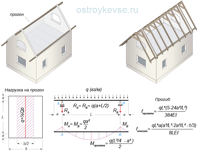
A prerequisite for installing layered rafters is to provide their upper part with support. In single-pitch roofs, this issue is solved simply: the walls are built at different heights, mauerlat beams are laid on them, on which rafters are in turn laid. In a gable roof you can do the same: build interior wall to the required height and lay the Mauerlat on it. Then lay the rafters on the low external and high internal walls. However, this decision limits the layout options for the attic space, which is increasingly being used as an attic. And for ordinary attic roofs, this option is not profitable, because... requires significant financial costs for the construction of a high internal capital wall. Therefore, in the attic, the internal wall is replaced with a horizontal beam mounted on supports or supported on the opposing gables of the walls. A horizontal beam laid on a roof is called a purlin.
The name itself: purlin, suggests that this beam is “thrown” from wall to wall, although in reality, for example, in hip roofs it may be shorter. The simplest design solution for installing a ridge girder is to lay a powerful beam on the gables of the walls without any additional supports (Fig. 24.1).
Rice. 24.1. An example of installing a ridge girder, without additional supports, on the attic walls
In this case, to calculate the cross-sections of the purlins, the load acting on them must be collected from half the horizontal projection of the roof area.
In buildings with large sizes the purlins turn out to be long and heavy, most likely they will have to be mounted crane. To make a purlin, find flat timber from solid wood longer than 6 m is quite problematic, so for these purposes it is better to use a laminated beam or log. In any case, the ends of the purlins, walled up in the walls of the gables, must be treated with antiseptics and wrapped in rolled waterproofing material. The ends of solid wood beams are beveled at an angle of approximately 60° and left open; in the niche they should not rest against the wall material (Fig. 25). Bevelling the end of the beam increases the end area and promotes better moisture exchange throughout the beam. If the purlin passes through the wall, then where it rests on the wall, it is also wrapped with waterproofing material. Beams are passed through the walls for architectural reasons in order to provide an overhang of the roof over the gables, although this can also be achieved by moving the sheathing beyond the wall. Purlins passed through the wall form unloading consoles. The pressure load on the console tries to bend the girder upward, and the load acting on the span tries to bend it downward. Thus, the total deflection of the purlin in the middle of the span becomes smaller (Fig. 24.2).
 rice. 24.2. Run with consoles
 If you use a log as a purlin, then it is not necessary to cut it into two edges; it is enough to trim it at the place where the rafters support and at the place where the purlin rests on the walls. It is not advisable to make long purlins made of solid wood; they are designed for strength and deflection; however, they can bend under their own weight. It is better to replace them with construction trusses.
The cross section of the purlin is selected according to calculations based on the first and second limit states - for destruction and for deflection. A beam working in bending must meet the following conditions.
1. The internal stress that arises in it during bending from the application of an external load should not exceed the design bending resistance of wood:
σ = M/W ≤ R bend, (1)
where σ - internal tension, kg/cm²; M - maximum bending moment, kg×m (kg×100cm); W - moment of resistance of the section of the rafter leg to bending W = bh²/6, cm³; R bend - the calculated bending resistance of wood, kg/cm² (accepted according to the SNiP II-25-80 table " Wooden structures"or according to the table on the website page);
2. The amount of deflection of the beam should not exceed the normalized deflection:
f = 5qL⁴/384EI ≤ f nor, (2)
where E is the modulus of elasticity of wood, for spruce and pine it is 100,000 kg/cm²; I - moment of inertia (a measure of the inertia of a body during bending), for rectangular section equal to bh³/12 (b and h are the width and height of the beam section), cm⁴; f norm - the normalized deflection of wooden rafters and purlins is L/200 (1/200 of the length of the checked beam span L), cm, sheathing bars and cantilever beams- L/150, bearing elements of valleys - L/400.
First, the bending moments M (kg × cm) are calculated. If the calculation diagram shows several moments, then all are calculated and the largest is selected. Further, by means of simple mathematical transformations of formula (1), which we omit, we obtain that the dimensions of the beam section can be found by specifying one of its parameters. For example, arbitrarily setting the thickness of the beam from which the beam will be made, we find its height using formula (3):
h = √6W/b , (3)
where b (cm) is the width of the beam section; W (cm³) - the moment of resistance of the beam to bending, calculated by the formula: W = M/R bend (where M (kg × cm) is the maximum bending moment, and R bend is the bending resistance of the wood, for spruce and pine R bend = 130 kg /cm²).
You can, conversely, arbitrarily set the height of the beam and find its width:
b = 6W/h²
After this, the beam with the calculated parameters of width and height according to formula (2) is checked for deflection. Here it is necessary to focus your attention: in terms of load-bearing capacity, the rafter is calculated based on the highest stress, that is, the maximum bending moment, and the section that is located on the longest span is checked for deflection, that is, on the section where the greatest distance between the supports is. The deflection for all: one-, two- and three-span beams is easiest to check using formula (2), that is, as for single-span beams. For two- and three-span continuous beams, such a deflection test will show a slightly incorrect result (slightly larger than it actually will be), but this will only increase the safety margin of the beam. For a more accurate calculation, you need to use deflection formulas for the corresponding design scheme. For example, such a formula is indicated in Figure 25. But we repeat once again that it is better to include a certain margin of safety in the calculation and consider the deflection according to the simple formula (2) at a distance L equal to itself long span between the supports, than to find the formula corresponding to the design load diagram. And one more thing you need to pay attention to is that according to the old SNiP 2.01.07-85, both calculations (for bearing capacity and for deflection) were carried out for the same load. The new SNiP 2.01.07-85 states that the snow load for calculating deflection must be taken with a coefficient of 0.7.
 rice. 25. Example of the location of purlins on a T-shaped roof
 If, after checking the beam for deflection, it is no more than L/200 in the longest section, then the section is left as it turned out. If the deflection is greater than the standard one, we increase the height of the beam or place additional supports under it, but the cross-section must be recalculated again according to the appropriate design scheme (taking into account the introduced supports).
The most difficult thing in this calculation is not to get confused in the units of measurement (in converting meters to centimeters), but everything else... Multiplying and dividing several numbers on a calculator does not require much knowledge.
Ultimately, only two numbers will appear: the width and height of the purlins required for a given load, which are rounded up to the nearest whole number.
If a log is used instead of a beam (solid, glued or assembled on an MZP), then it should be taken into account that when working in bending, due to the preservation of the fibers, the load-bearing capacity of the log is higher than that of the timber and amounts to 160 kg/cm².
Moment of inertia and resistance round section determined by the formulas: I = 0.04909d⁴; W = 0.09817d³, where d is the diameter of the log at the top, cm.
Moments of resistance and inertia of a hewn log:
for one edge, equal to I = 0.04758d⁴, W = 0.09593d³, for two edges - I = 0.04611d⁴; W = 0.09781d³, with a panel width of d/3;
for one edge, equal to I = 0.04415d⁴, W = 0.09077d³, for two edges - I = 0.03949d⁴; W = 0.09120d³, with a panel width of d/2.
The height of the purlins and rafters, depending on the loads and the architectural design of the roof, can be very diverse. In addition, the forces pressing on the walls, especially when it comes to purlins, reach large values, so the roof, like everything else, must be designed in advance, even before the house is built. For example, in the layout of a house, you can introduce an internal load-bearing wall and relieve the purlins, or make capitals on the gables of the walls, put slopes under the purlins and thereby reduce their deflection. Otherwise, it will be quite difficult to connect purlins of different heights to each other and to coordinate the elevations with the gables of the walls.
When using long and heavy runs, you can use the so-called “construction lift”. This is the manufacture of a beam in the form of a rocker arm. The height of the “rocker arm” is made equal to the standard deflection of the purlin. The loaded beam will bend and become level. The method came to us from our ancestors. They're in log houses when laying the mats and beams (beams), the logs were undercut from below, along the entire length, making the undercut deeper in the middle part, and, if necessary, undercutting the edges of the beams from above. Over time, the rocker-shaped beams sagged under their own weight and became straight. This technological technique is used quite often, for example, prestressed reinforced concrete structures are made. IN Everyday life you simply don’t notice it, because the structures bend, and the already small construction rise becomes completely invisible to the eye. To reduce the deflection of the beam, you can also introduce additional struts under it. If it is impossible to install struts or make a “construction lift,” you can increase the rigidity of the beam by changing its section: to a T-beam, I-beam or lattice - a truss with parallel chords, or change the cross-section by placing cantilever beams under the supports, that is, making its bottom in the form of an imperfect arch.
The support of the purlins on the wall is ensured by a transverse side support and must be designed for wood compression. In most cases it is enough to provide desired depth support and place a wooden lining under the block on two layers of roofing material (waterproofing, etc.). However, it is still necessary to carry out a verification calculation of wood for crushing. If the support does not provide the required area at which collapse will not occur, the area of the wooden pad must be increased, and its height should distribute the load at an angle of 45°. The crushing stress is calculated using the formula:
N/F cm ≤ R c.90° ,
where N is the pressure force on the support, kg; F cm - crushing area, cm²; R cm90 - calculated resistance to wood crushing across the grain (for pine and spruce R cm90 = 30 kg/cm²).
Need to pay Special attention on the wall under the support of the ridge girder. If there is a window below, then from the top of the lintel to the bottom of the purlin there must be at least 6 rows of reinforced masonry, otherwise reinforced concrete lintels must be laid above the window inside pediment. If the layout of the house allows, the ridge purlins should not be made long and heavy; it is better to divide them into two single-span purlins or leave one and add a support under it. For example, the layout of the house shown in Figure 25 involves installing a partition in the room under the second purlin. This means that you can install a truss truss in the partition and unload the ridge girder, and then hide the truss with sheathing, say, plasterboard.
 rice. 26. Rafterless roof
 Another way to unload ridge purlins is that you can simply increase the number of stacked purlins, for example, install one or two unloading purlins along the roof slopes. With a significant increase in the number of beams, the question arises: why do we need rafters here at all? The sheathing can be done directly along the purlins. This is true. Such roofs are called rafterless (Fig. 26). However, in attic insulated roofs the issue of drying the insulation becomes acute, so something like rafters will still have to be made. To ensure air ventilation, it will be necessary to fill the purlins with wooden blocks, for example, 50×50 or 40×50 mm, along the slopes (in the same direction as the rafters are laid), thereby providing an air outlet with a height of 50 or 40 mm.