Great Encyclopedia of Oil and Gas. Underground water tap
For a water supply or gas pipeline, it is most convenient to embed ball valve underground installation made of plastic. This design can provide a fairly long period of operation, and without any problems with maintenance.
There are many options for materials for such shut-off valves, but plastic is the most convenient, as it is not at all afraid of dampness and corrosion. We will tell you how to install it and demonstrate a thematic video in this article.
PE taps
Description

- much cheaper than metal ones, so most settlements and various industrial facilities cannot do without communication routes made of this material. In addition, the price of a PE tap is much lower than that of a steel analogue, but its service life is immeasurably longer, which also plays an important role in the choice of materials for pipelines.
- The widespread use of such a mechanism is also due to its fairly wide range of diameters.— it can be mounted on pipes with a cross-section from 20 to 315 mm and it can operate at temperatures from -20 ⁰C to +40 ⁰C, this is acceptable for any region of the Russian Federation for underground installation.

- In addition, a ball valve for underground installation can be mounted without constructing a special well for this purpose - to adjust it, it is enough to remove the control mechanism outside, and the assembly itself can be covered with earth. The distance to the ground surface from the pipe can range from 1650 mm to 2750 mm.
- The telescope rod is extended due to a square hollow profile, at the end of which a hexagonal bushing is welded, which is installed on the crane axis and rotated using a square/hexagonal metal rod.
- An underground ball valve is made from polymer materials (the design is intended for butt welding, or for). Output pipes this mechanism made from PE 100 SDR11 - this is quite enough for gas pipelines with a pressure of 10 bar and water pipelines with a pressure of 18 bar.
Note. A protective polyethylene casing made of two thin-walled pipes is installed on the extension cord.
They can move freely one into another.
Technical characteristics of some cranes

Table for SDR11

PE ball valves
| Diameter (mm) | 20 | 0,560 | 20 | 0,560 | 20 | 0,560 | 20 | 0,560 | 20 | 0,560 | 20 | 0,560 | 20 | 0,560 | 20 | 0,560 | 20 | 0,560 |
| Weight (kg) | 25 | 0,560 | 25 | 0,560 | 25 | 0,560 | 25 | 0,560 | 25 | 0,560 | 25 | 0,560 | 25 | 0,560 | 25 | 0,560 | 25 | 0,560 |
Dimensions. Standard
PE valve without purge


Installation nuances
Note. In the Russian Federation, at the moment, a water or underground gas tap is not widely used.
Nevertheless, many construction organizations are showing a healthy interest in such structural devices.

These shut-off valves in above-ground or underground (using wells) versions can be used in the gas industry. But at the same time, the instructions do not recommend using wells along the route.
The thing is that the rules for working in these tanks and recommendations for opening them significantly complicate the operation of shut-off valves of this type.
OAO Gazprom has developed certain technical standards, in which the installation of shut-off valves made of polyethylene (price is not taken into account) is preferably carried out without wells.

Under-hatch installation
There is a standard STO GAZPROM 2-2.1-093-2006, which demonstrates (illustrates) solutions for the design, construction and reconstruction of polyethylene pipelines for gas mains.
It describes a variety of installation options for PE ball valves that can be performed:
- Directly on the roadway (in the middle of the road);
- Directly on the roadway (in the middle of the road) and on pedestrian sidewalks, as well as in the park area;
- Under a carpet (turf) in a park area or forest belt.
Conclusion
Do-it-yourself installation of PE taps for home plumbing is currently somewhat difficult, since there is no special equipment for this, which is supplied through a network of hardware stores.
If we talk about plastic, then for the private sector preference is given to polypropylene and at the moment this material fully satisfies the needs of private sector residents.
Underground water supply
Page 1
Underground water pipelines must be laid below the freezing depth of the soil. The depth of installation is also dictated by the need to protect pipes from dynamic loads created by moving vehicles.
To connect underground water pipelines in Czechoslovakia, Wimer connections are used, and for glass concrete pipes, after putting on a rubber cuff, the joint is reinforced with a metal spiral and filled with cement mortar. For large diameter pipelines, standard plumbing cast iron parts are used instead of undeveloped glass fittings.
Galvanized pipes are often used for underground water pipes. In table 7.4 shows the test results that were obtained on galvanized pipes and plates after testing in the ground in different places.
For fire extinguishing, water is taken from underground water supply, natural or artificial reservoirs and supplied to the fire site by fire trucks. In production premises, internal fire hydrants with one (or two) rubberized hose and barrel are installed in wall niches or cabinets in such a way that each production room it was possible to supply at least two jets of 2 5 l/s from two adjacent taps.
Cast iron pressure pipes are designed for underground water pipelines and pressure sewer collectors; are made of gray cast iron by centrifugal and semi-continuous casting.
Reinforced concrete pipes are used for the construction of underground water pipelines, sewage systems, and collectors for cable laying.
The operational reliability of structures is at risk. This applies, for example, to underground water pipes, which may fail due to corrosion. Other examples would be electronic equipment, for example control functions which may be affected by corrosion; maritime oil platforms operating in extremely corrosive conditions; nuclear power plants, where corrosion damage can lead to costly accidents, in some cases completely unacceptable from a safety point of view. Production interruptions caused by corrosion are becoming increasingly important to society as more and more complex designs.
The location of plastic gas pipeline pipes underground is determined by the project. The layout of the gas pipeline route is carried out similarly to the layout of the underground water supply route described above. Excavation work for digging trenches is carried out using narrow-trench excavators. On the side free from soil, lay out the materials prepared for installation. plastic pipes.
In 2003, after field tests of a prototype of the MI-31 in-pipe magnetic introscope carried out on the basis of MGP Mosvodokanal, it was concluded that the MI-31 design allows continuous monitoring of the entire length of a pipeline section with a resolution of 2 mm and a productivity of 0 5 m/s. The proposed technology makes it possible to identify both through and non-through defects in the wall of an underground water pipeline located on the inner and outer surface of the pipe, and to determine them mutual arrangement and geometric dimensions without opening the pipeline route.
The work of Hudson and Acock [141] describes five years of testing of galvanized steel pipes at five various places, conducted by BISRA. At all test locations, galvanized pipes showed slightly higher corrosion resistance than steel pipes. Galvanized pipes are not large diameter often used in underground water pipes on farms and other similar applications.
In all industrialized countries, all higher value The problem of protecting metal from corrosion arises. Among the various methods used to solve it, a special place is occupied by electrochemical (cathodic) protection systems, which are widely used to prevent the destruction of metal structures operated in natural water and soil conditions. The scope of cathodic protection is very wide; it covers underground water pipelines, gas, oil and product pipelines and metal pipelines for other purposes laid in the ground, underground communication cables, power cables with a metal sheath and armor, cables laid in pipes filled with compressed gas or oil, various reservoirs - storage facilities and tanks, river and sea vessels, port equipment, installations drinking water and various devices chemical industry needing internal protection.
Some data regarding the dimensions and weight of pipes are given in table. 6.16. The pipes are mainly supplied in 5 m lengths with smooth ends - so-called industrial pipes. The pipes are connected using glued couplings or fittings. At the customer's request, they are equipped at one end with a coupling connected to the pipe with glue. It is recommended to use in underground water pipelines rubber seals contact connections.
Pages: 1
www.ngpedia.ru
Polyethylene ball valve for underground installation brand DAEYOUN
An underground polyethylene ball valve is designed for installation on gas and water pipelines located underground, and acts as a locking mechanism. The working environment is controlled by opening or closing the shut-off valve.
Thanks to the auxiliary bearing, the ball moves smoothly after being installed in the ground.
These taps have a full passage of the working medium passing through them. For taps with a diameter over 200 mm, a mechanical operator is installed, which reduces the torque and ensures smooth opening/closing.
The crane structure is made of plastic material(PE 100), which provides the most maximum corrosion resistance, thereby extending the service life to 50 years.
Unlike underground steel cranes, underground polyethylene cranes have a removable telescopic rod, which can vary from 1.2 m to 2.0 m.
Polyethylene ball valves can be manufactured with diameters from 20 mm to 400 mm.
A polyethylene underground valve is connected to the pipeline by butt or electric welding, and has a strong, hermetic connection that does not allow the working environment to pass through.
Two (and in the case of large diameter valves, three) sealing rings installed between the bearing and the housing, especially which is located at the bottom of the bearing, uniquely increases the level of tightness.
The pin between the adapter and the bearing securely fixes the tap during opening and closing.
The sealing ring installed between the adapter and the body prevents soil and dust from entering the tap. Polyethylene ball valves for underground installation can be installed on a gas pipeline with a pressure of no more than 10 bar, and a water supply with a pressure of no more than 16 bar, and in the temperature range from -29ºС to 60ºС.
To facilitate the rotation of the shut-off element in large-diameter taps, one-way and two-way blowdowns can be used.
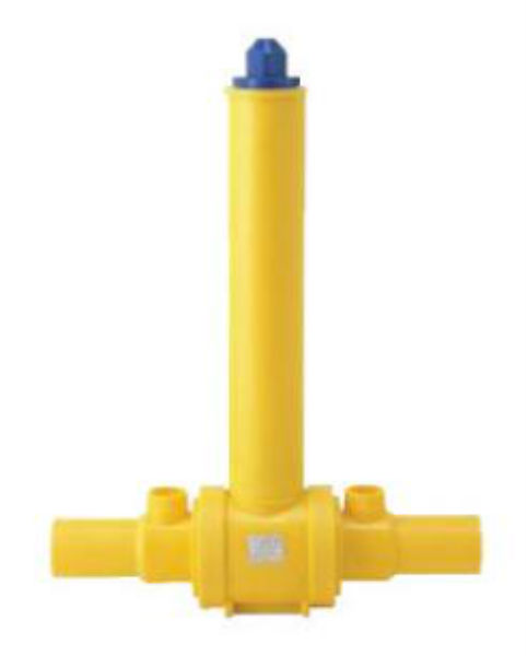
Polyethylene ball valve without extension rod.
Polyethylene ball valve, extended, for underground installation.
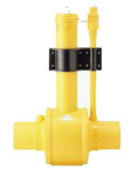
Polyethylene ball valve for underground installation, with a one-way purge system.
Polyethylene ball valve for underground installation, with a double-sided purge system.
Material and properties of parts:
Material: polyethylene HDPE (HDPE) – polyethylene low pressure(high density)
Characteristics: the housing is designed taking into account the installation of the ball inside, the tightness and tightness of the bearing, ball seat, retainer, and O-rings. The bottom of the housing is machined tightly for easy installation. The bearing and adapter are located in the center of the bottom. Interior The housings are machined cleanly and accurately using CNC machines to ensure each part fits securely.
2. Bells
Material: polyethylene(MDPE: polyethylene medium density)
Characteristics: sockets are made taking into account the connection with a specific pipe. Manufactured with grooves for inserting heat conductors. At the customer's choice, it is possible to install it for any type of tap (without blowing, with one, two blows).
Material: polypropylene (POLYPROPYLENE: PP)
Characteristics: the ball is made using a CNC machine. The ovality of the ball does not exceed 30㎛, due to which there is no damage to the seat due to friction. The applied silicone grease allows work even with minimal torque.
4. Bearing
Material: acetal (ACETAL)
Characteristics: bearings are made of acetal parts, molded from extruded blanks according to digital control, taking into account stability, elongation, and dimensional stability. Increased tightness thanks to 3 O-rings - between the middle of the rod and the body (2 pcs.) and between the lower part of the rod and the body (1 pc.).
5. Ball seat
Material: NBR (RUBBER)
Characteristics: The ball seat, O-ring, and other rubber parts are made of nitrile butadiene rubber (NBR) to improve elasticity, elongation, and durability during operation under standard temperature and pressure ranges.
6. Lock
Material: polypropylene (POLYPROPLENE)
Feature: These elastic retainers are injection molded polypropylene and are inserted on both sides of the body and hold the ball seat firmly.
7. Adapter
Material: polypropylene(POLYPROPLENE)
Characteristics: Made of polypropylene by injection molding, taking into account the high load when the ball is released, including tensile force, elongation, impact resistance. There is a locking device at the bottom of the adapter that prevents rotation beyond 90°. An O-ring is inserted inside the adapter, with which it is possible to prevent the entry of foreign particles. The adapter can withstand heavy loads.
8. Auxiliary rod
Material: acetal (ACETAL)
Feature: Provides simple, easy operation even when the crane is buried deep in the ground. Designed to withstand the heavy load that occurs at the bottom of the stem when the ball is released (which even exceeds the load at the top!). The lower part is made of acetal by injection molding and withstands the greatest excess torque when opening/closing the tap.
9. Mechanical operator
Material: polyethylene, etc.
Characteristics: designed for large diameter taps (more than 200mm), installed on an auxiliary rod with 4 gearboxes to reduce torque. Resistant and anti-corrosion. The flywheel opens/closes easily with 2½ turns. The mechanism is equipped safety device to prevent unnecessary stress when completing opening/closing (internal parts can be replaced if they break).


Return to list
www.neftegazholding.com
location options and installation rules
Organization of autonomous water supply for suburban area provides the opportunity to enjoy the benefits of civilization regardless of the presence of centralized communications. Most often, in private bathhouses, a cold water supply system is installed from a well or well, and a storage tank is used to ensure water pressure. It is also required to collect reserve water in case of power outages. Where is the best place to place a storage tank for cold water so that the bath water supply system works properly and does not create problems for the owners.
Storage tank in autonomous water supply
An individual water supply system with a storage tank is extremely simple. Water from a well or well is pumped by a pump, the type of which depends on the height of the water level in the source. Mostly, country farms use quiet submersible pumps or stations with an ejector and their own hydraulic tank.
Pumping station good if you country building has its own basement. Or there is enough space on the site to build a shed for its placement, because... This is quite “sounding” equipment. But purchasing a station can save you from installing a storage tank if its built-in tank has a volume sufficient for daily consumption.

Surface pumps are also unattractive in terms of sound interference, but they are significantly cheaper. True, they pump water only from wells and wells with a high water surface or from nearby lakes, ponds, and rivers. For surface pumps, the main thing is that the height difference between the point of water intake from the source and the point of delivery to the storage tank does not exceed 6-7 m, which is extremely rare in reality.
Thanks to the inclusion of a storage tank in the autonomous water supply system, the water pumped out by the pump does not immediately flow into the taps, the tank on the sauna stove, the boiler, the shower, the toilet tank and other water points. First, water is accumulated in the form of a reserve approximately equal to the volume of the storage tank. The water reserve in the storage tank makes it possible to use several plumbing fixtures simultaneously. Without a supply of water, normal pressure for use would be in only one open tap, and that’s not a fact.
In an autonomous water supply system, a cold water storage tank, in theory, performs the function of a water tower. The water supply also allows you to reasonably limit the number of pump turns on/off, which is absolutely beneficial for any equipment. The storage tank is equipped with a mechanical, electronic or electric float valve to pump equipment didn't work in vain because:
- when the water pumped into the tank reaches the maximum level, the float signals that the pump is turned off;
- when the level drops, a command is given to turn on the pump to replenish the used supply.
This eliminates unnecessary work of equipment and overflows. Instead of a valve, folk craftsmen have contrived to use a toilet float mechanism, which simply closes the opening for water flow when the required volume is exceeded. The pump can be turned on/off manually or automatically. You will also need a “dry running” relay to stop the pump if it is completely empty storage tank.

In the cold water storage tank there are holes required to connect the pipeline and to ensure normal operation of the system as a whole, these are:
- hole for connecting the supply pipe. Before entering the supply pipe, it is recommended to install a coarse mesh filter to mechanically prevent small animals and large grains of sand from entering the tank;
- a hole for an overflow pipe through which excess water is discharged from the tank into the sewer system. Arrange an overflow a couple of cm below the float valve in case the latter does not work for some reason;
- one or more openings for outgoing pipes supplying the water heater and cold water collection points. They are often located in the lower third of the tank, but there must be at least 10 cm between the bottom of the storage tank and the outlet points so that the inevitable groundwater sediment did not enter the main line;
- a ventilation hole in the lid of the drive, if the lid closes it to prevent dust, insects and other contaminants from entering the container.
The hole for entering the supply pipe is sometimes located in the upper part of the tank opposite the installation location of the float valve. However, in order to completely drain water from the storage tank in order to preserve the autonomous water supply system, it is recommended to place the inlet pipe opening in the lower zone of the tank. It still needs to be equipped with a drain valve. If the lower location of the supply pipe inlet cannot be used for any reason technical reasons, then to preserve the water supply system with a storage tank, an additional drain hole will be required.

Methods for installing storage tanks
The location of the reserve tank determines the type of water supply wiring and the set of equipment required for trouble-free operation of the cold water supply system of the bathhouse. In low-rise construction, two main options for constructing water pipelines with storage are used, these are:
- upper scheme, according to which the reserve tank is installed on the highest possible platform: on flat roof, a specially constructed overpass, on brackets under the ceiling, a concrete podium inside or outside a building, an attic, etc. The installation height of the drive is top diagram– parameter adopted according to individual technical conditions. Drives year-round water pipelines must be insulated if they were installed in unheated room;
- the lower diagram, according to which a cold water tank is buried in the ground in the basement of a building or on a site, if water is supposed to be taken from the tank for irrigation and other household needs. To install a year-round water supply, the storage tank is buried below the freezing zone; for summer water supply, it is enough to position the tank so that between its upper plane and earth's surface was at least 0.5 m. You should also provide a lower entry for the incoming pipe and install a drain device on it.

Often, independent home craftsmen prefer the top scheme. It is easier to build a water pipeline with an upper storage tank with your own hands, and it will not require less expenses than an underground one. Water is distributed to water distribution points by gravity without additional devices stimulating its movement. The only disadvantage of the upper scheme is quite weak pressure, depending on the installation height of the storage tank. To create a pressure of 0.1 atmosphere, the tank will need to be raised by 1 m, for 0.5 atm. at 5 m. Do not forget that for work, for work washing machine, for example, you need a water column pressure of 1 atm.
A water supply system with a bottom storage tank is sometimes classified as a system with pneumatic capabilities. The pump pumps water into the underground container, which compresses the air cushion there. When the water in the tank reaches a certain level, compressed air will begin to push it upward to the water points. True, the pneumatic capabilities of water pipes with bottom wiring are rarely relied upon. They are too insignificant. Most often for supplying water from stable pressure from the lower storage tank, an additional one is used, installed directly into the container submersible pump drainage type with float switch.

Optimal material for storage tank
The volume of the storage tank should be equal to one-time water consumption. In this aspect, everyone's preferences differ. Therefore, the acceptable capacity of tanks ranges from 100 to 1000 liters. The requirements for storage tanks for cold water supply determine the upcoming operating conditions. In any case, the container must be sealed, wear-resistant, stable, and inert to chemical and biological contaminants.
The following can be used as a storage device in organizing autonomous water supply:
- a homemade welded tank with or without a lid, if the water quality does not bother summer cottage owners too much;
- factory opaque plastic container, instead of which it is quite acceptable to use Eurocubes connected to each other by pipes;
- a concrete cavity poured into underground or above-ground formwork.
You can weld a tank with your own hands from sheet steel, aluminum, or from a piece of large-diameter pipe. A budget alternative would be a metal barrel or old bath with well-preserved enamel, if you plan to organize a temporary summer water supply system with an upper storage tank. You will still need to make a lid for it with ventilation hole.
The storage material is selected based on its installation location:
- in the upper scheme, a ready-made plastic tank or a metal container of your own making can be used. The structure on which the drive will be installed must first be strengthened, because it will have to support from 100 to 1000 kg of additional weight. If the tank is located outside, it must be carefully attached to the overpass so that after draining the water, the empty tank does not turn over by the wind;
- in the lower bath water supply scheme with a storage tank, the best choice would be a ready-made container made of food-grade plastic or Eurocubes. A tank with concrete walls is ideal, which can also serve as a protective “shell” for plastic tank. Concrete protection will protect empty or half empty plastic product from soil pressure. Those. two in one is the perfect choice.
If the owners of a stationary bath water supply with a bottom storage tank leave their beloved estate for several days in winter, the water from the underground reservoir does not need to be drained. It won't bloom because its surroundings resemble a thermos, and it won't freeze because... the tank is below the freezing horizon. But cleaning an underground tank can create problems if the tank is not equipped with a maintenance hatch and the inlet pipe is not installed at the level of the bottom of the tank.

Diaphragm accumulator instead of accumulator
A hydraulic accumulator with a membrane is a high-tech descendant of conventional accumulators. His cost is not very humane, but he solves all issues with the supply, supply of water and ensuring pressure independently. Diaphragm tank It is a metal container divided inside into two parts by an elastic bag-like partition-membrane. Air or nitrogen is pumped into one part of the tank. Traditionally, the gaseous medium has a pressure of 2 atmospheres, but it can be adjusted.
When the pump operates, water fills the second part of the container, stretches the membrane and compresses the gaseous medium, which, when the tap is opened, pushes water to the points of consumption. When the hydraulic accumulator is filled according to the specified parameters, it automatically turns off the pump. When the tank is emptied and the pressure in the tank concomitantly drops, the automation turns on the pumping equipment again.

The membrane tank is installed in front of the pipeline branches. It can be installed in a well caisson, in a well pit or directly in a bathhouse. At the entrance to the container there should be a check valve to prevent the pumped water from flowing back into the source, and at the outlet there should be a pressure gauge to check the pressure. To remove air from the system, the hydraulic accumulator is equipped with an automatic valve. The membrane container operates in dynamic mode, so you don’t have to get carried away with its internal volumes being too large.
A membrane-type hydraulic tank is a very useful thing in the household, but not cheap. You should not undertake its installation and configuration without having experience in this matter. Incorrect pressure setting may cause diaphragm rupture. The fastening of a device that vibrates during operation must be very reliable. Without knowledge of the technological intricacies of connecting, the tank will be quite disturbing unpleasant sound. But the manual installation of a conventional storage tank for supplying water to the bathhouse is highly recommended and economically justified.

How to install a simple top drive
Let's look at a common option with the location of the drive in the attic. This means we make it ourselves or choose a container that can fit into attic hatch or a window. Limitations on volume and dimensions are not a problem for those who, during the construction process, thought through the design of the water supply system. Then the container can be installed in advance on the upper floor if it will not interfere with construction rafter system.

Now we will look in detail at how to install and connect a cold water tank to a year-round bathhouse:
- We will first strengthen the base by laying thick boards on the beams of the upper floor;
- place the container in its proper place;
- install the float valve. To do this, mark a point, 7-7.5 cm away from the top edge of the container, and cut a hole of the size we need. We insert the valve shank into the formed hole, having previously placed a plastic washer on it. On the other side of the tank wall, first put on the stiffening plate, then the second washer and screw on the nut. We tighten the fasteners and screw the connector to the shank so that the supply pipe can be connected;
- We drill holes for outgoing pipes according to their sizes. From the inside of the tank, insert a connector with a plastic washer into each hole. We strengthen the thread by screwing on two or three layers of FUM tape, after which we put on the washer and screw on the nut;
- We install a shut-off valve into each outgoing pipe;
- We make an overflow, for which we mark a point 2-2.5 cm below the marking point of the float valve and drill a hole. The overflow pipe is discharged into the sewer; we attach it to the tank with connectors similar to the previous one;
- We bring pipes to the tank and fix them using the compression method. We attach the newly created sections of the pipeline to walls or beams;
- we fill the reservoir with water to check the tightness of the connections, at the same time we adjust the position of the float in accordance with the position of the overflow;
- We insulate the container by attaching long pieces of polystyrene around the walls or wrapping it in mineral wool.

Video instructions for installing an underground storage tank
In this democratic way you can organize cold water supply with a storage tank for a bathhouse. Essentially this general recommendations– a kind of food for thought that should be adjusted according to technical features buildings.
Ball valves are a type of pipeline shut-off valves that are designed for gaseous and liquid media. They are used in both domestic and industrial settings. Cranes have become so widespread due to their reliability, durability and simplicity of design.

Distinctive features
Ball valves are compact, practical, neat and aesthetically pleasing. They are incredibly easy to use: just turn the special handle 90 degrees. This way you can instantly stop the supply of water or gas. This factor is especially important when it comes to any accidents and leaks in gas or water pipes.
It is also important that the faucet is made of durable material that is resistant to corrosion, mechanical damage and exposure to aggressive environments. In addition, the taps are wear-resistant and have a long service life. If necessary, they can be easily repaired without significant costs.


Design
The taps consist of the following elements:
- frame;
- pens;
- housing and adjusting nut;
- Teflon sealing seat;
- rod with rubber seal;
- sealing washer.
The passage of the necessary medium is carried out due to a special valve - a part in the form of a metal ball with a through cylindrical hole in the middle. The size of this hole matches the inside diameter of the attached pipe. In this regard, the valves are called full bore.
Operating the ball valve is extremely simple. If you open it completely, there will be almost no hydraulic losses in the circulation flow. This feature reduces pipe wear and increases their service life. To completely block the flow, simply turn the control knob 90 degrees.

Kinds
By throughput:
- full bore – 90–100%;
- partial bore – 40–50%;
- standard – 70–80%.
According to the material of manufacture:
- brass;
- plastic;
- other alloys.


Each material has certain advantages and disadvantages. Choice specific type depends on the purpose of the crane.
By type of fastening:
- coupling;
- flanged;
- welded;
- combined.

Scope of application
Coupling
They are used to equip gas, water supply and heating systems of residential buildings and public buildings. Most often used for standard radiators, even under carpet. Coupling taps are convenient and easy to use, practical, compact, easy and quick to install without special equipment. Suitable for pipes with a diametrical cross-section of no more than 40 millimeters. If the pipe is larger, it is better to opt for a flanged valve.


Flanged
Mounted on pipes with a diameter of over 5 centimeters. To achieve maximum tightness, special seals are used during their installation. This type of spherical structures is characterized by increased strength indicators. They are either collapsible or non-dismountable. In the first case, the design consists of two elements (to ensure easy and quick disassembly). This is necessary in order to easily replace a faulty structural part. Non-separable flanged options have an integral body, and if any part is damaged, the valve must be completely replaced.

Welded
Most often, such ball valves are mounted in closed places and cannot be dismantled. For example, they are often used in the construction of buildings. This is the main difference between the welded type and all others. The structure is created by welding.

Combined
They imply several options for attaching to pipes. The number of branch pipes for combined valves is different; therefore, they are: through, angular, multi-way. The latter option is simply irreplaceable in situations where there is a need to simultaneously mix several different environments.
There is another, much less common type of ball valve - union valve. It is used in various industries industry: chemical, food, etc. Main feature Such structures are capable of repeated dismantling. They are simple to implement and easy to use.

Choice ball valve directly depends on what it will be used for and how it will be attached.
- If you need a strong and durable ball valve that is resistant to corrosion and temperature changes, then it is better to opt for a brass design. This option is ideal for hot water pipes or for the construction of underground structures.
- A plastic or polyethylene ball valve can easily become deformed or become unusable when exposed to high temperatures. Therefore, it is best used for pipes with cold water or gas.
When installing a ball valve underground, you do not need to build a special well - to adjust, you just need to remove the control mechanism and fill the assembly with soil.


To see how a ball valve works, see the following video.
Underground ball valve has found wide application in the field of installation of pipeline communications. It is used as a shut-off valve to shut off and regulate the flow of the working medium. Despite the simplicity of the design, it demonstrates high level reliability in operation, during its operation the presence of “stagnant” zones is excluded.

Underground cranes, presented on our website, have different purposes
- Equipping systems that transport aggressive and non-aggressive media;
- Control by means of a gearbox, but it is possible to equip it with pneumatic or electric drive;
- Operation under conditions of nominal pressure up to 16 MPa;
- Installation of communications in a wide range of diameters: 80-600 mm;
- Use on pipelines that are laid underground.
Design Features
The main working body underground ball valves serves as a shutter, which is a steel ball with through hole. When the shut-off element is open, the hole and the pipeline are parallel to the same axis. When the movement is blocked, the hole moves 90° and is located perpendicular to the pipe.
For the manufacture of fittings, alloy and stainless steel with high anti-corrosion properties are used. Elastic fluoroplastic is selected for sealing.
From design features underground cranes It is worth highlighting the presence of an extended rod. To connect the fittings to the pipeline, welding technology is used, which provides the following advantages:
- Tightness of communication;
- Reliability of the pipeline in operation
- No maintenance required.
When using this fittings, there is no need to create a manhole and enclosing structure. If there is a need to dismantle tap, then this is done by cutting off part of the pipes. During installation and dismantling work, the shutter must be left in the open position. Otherwise, the ball may be damaged. The fittings are selected depending on the operating conditions and technical characteristics pipeline system.


You can purchase from the StroyNefteGaz company underground ball valves for various pipelines. All models presented are different high quality performance and long service life.
For pipelines buried relative to the ground surface, an underground ball valve has been created driven by an electric motor, pneumatic cylinders, a gearbox or a T-shaped key. The body has a multi-layer anti-corrosion coating, the spindle extension is protected by a vertical shell pipe with a flange connection to the upper part of the valve body.
Design Features
Initially, the ball valve has more than 100 design options, each of which has its own marking in table No. 1 ST TsKBA 036 of 2007. For example, single-pipe 10nzh937p, coupling economy 10nzh12p, retro 10nzh11p, three-way 10nzh2p, welded 10s7p, all-metal monobody 10nzh13p, fitting 10nzh14p, reduction 10nzh24p, with leakage control 10s28p, with heating vom 10nzh29p, distribution 10s33p, and many other options.
Almost each of them is suitable for underground installation, but only after making special changes to the design. For example, installation inside a well and with simple backfilling with soil is possible. In the latter case, it is imperative to protect the extension cord with a tubular sheath along its entire length. The pipe is attached to the body with a flange, so a counter flange is required in the upper part.
Ball valve body
The design of the ball valve body depends on several objective factors:
- preparation method;
- development of design bureaus of a specific manufacturer’s plant;
- requirements of GOST, TU, OST and ST standards.
According to manufacturing technology, ball valves are divided into categories:
- in an all-metal non-separable body;
- two parts;
- of three elements.
In the first case, the body is turned on a machine, cast centrifugally into formwork, and welded from several tubular blanks or two stamped parts.
In the second version, the ball valve body is assembled on flanges from two vertical halves. In the latter case, the seat and ball are pulled together into a single package by side pipes through flanges using pins.
In addition, the body of an underground ball valve can be full bore or pressure reducing. In the first case inner diameter coincides with the cross-sectional size of the pipeline, the hydraulic resistance inside the pipeline is minimal. In the second option, the valves are narrowed by one standard size, that is, they can reduce the flow characteristics of the working medium; diagnostic and cleaning devices will not be able to pass through such a valve.
A collapsible body made of 2 or 3 parts is much more convenient from the point of view of servicing shut-off valves. At any stage of operation and during scheduled maintenance, you can clean the internal cavity or replace the seat rings. A non-separable housing is much more airtight and cheaper to produce.
Some manufacturers use original technical solutions in the design of ball valve bodies. For example, drainage system in the housing of large-diameter fittings allows you to drain condensate from the pipeline transporting natural gas.
When using hydraulic and pneumatic drives, they can be controlled from external sources and the transported medium itself. For this purpose, special holes are made in the housing and the drive is connected.
The bypass system allows you to safely equalize the pressure inside the valve cavity and behind the nozzles, which is especially important for ball valves DN 700 - 1400 mm.
The body material is carbon, alloy and stainless steel with the markings “c”, “hp” and “nzh”, respectively. Depending on the method of installing the ball valve underground, different protection of the body from aggressive environments is used:
- acrylic paint – has electrical insulating properties, protects the fittings from stray and induced currents;
- epoxy-based coal tar paint – resistant to electrical corrosion and mechanical damage;
- polyurethane foam coating - used for well-free installation directly into the ground;
- polymer paintwork– standard protection against corrosion and mechanical damage.
Large-sized ball valves for underground installations are mounted using cranes and manipulators. For hooking, fabric and cable slings are used, but additional load-bearing devices are usually not installed on the hull.
Locking unit
Initially, an underground ball valve belongs to the category of rotary valves. There are cut-off, shut-off, regulating, shut-off-reducing and regulating-cut-off modifications for specific operating conditions. The main features of ball valves are:
- movement of the spherical plug from one extreme position (“open”) to another (“closed”) during the rotation of the spindle by 90 degrees, which is why the valve is called half-turn;
- the plug is mounted in supports, a wear-resistant anti-corrosion coating is applied to its surface;
- the seats have a ring design that evenly distributes the pressure of the working medium onto the ball;
- Manufacturers provide lubricant supply to the spindle and seat assemblies.
By default, the basic package of large-diameter ball valves usually includes a combined drive with the ability to operate on gas or liquid media. This is the most economical option for reducing the main pipeline operating budget.
The design of the plug in the supports makes it possible to spring the seats to the spherical plug or use the pressure of the working medium itself for the same purpose. This ensures maximum class A tightness of the valve assembly on both sides of the valve. Secondary soft seals and special grooves into which the rings go are, in turn, responsible for the safety of the rings themselves.
Relieving pressure from the internal cavity of the valve body is only possible when transporting liquid media. For gas pipelines, taps are produced with a sealed internal cavity without drainage or bypass.
The climatic version according to GOST 15150 - “UHL”, “HL”, “U” or “T” is chosen by the customer himself.
Spindle and extension
Manufacturers of underground ball valves usually provide spindle extensions in the following sizes:
- less than 1000 mm;
- 1001 – 1500 mm;
- 1501 – 2000 mm;
- 2001 – 2500 mm;
- 2501 – 3000 mm.
In this case, the lower part of the tubular shell of the spindle extension is fixed with bolts with a mating flange on the ball valve body. A T-shaped wrench (usually in fire hydrants and chemical storage systems), a pneumatic or hydraulic drive, a gearbox with a bevel, spur and worm gear, an electric drive or a hand wheel/handle is put on the upper end of the extension.
If the hydraulic pneumatic drive is controlled by the working medium from the main pipeline, copper or steel tubes are additionally used, tying the valve body with the branch pipes of the drive device. The tubular shell of the spindle extension is covered with the same protective compounds that protect the body of the ball valve - paints or polymer materials.
Drive device
For an underground ball valve, operation with all types of drives specified in the table of figures of GOST R 5272 of 2007 is allowed:
- 0 – remote control;
- 3 – 5 – mechanical gearbox with worm, cylindrical and bevel gear, respectively;
- 6 – pneumatic drive;
- 7 – hydraulic drive;
- 8 – electromagnetic solenoid;
- 9 – electric drive.
In addition, drives can be installed upon customer request combined type– electrohydraulic, pneumohydraulic. For diameters from 400 mm, AAZK automatic machines are often used, closing the tap without operator intervention. For piston drives with liquid and gas working media, control units BUK, BUP and EPUU with power supply from 24 V, 110 V or 220 V DC are required.
To be used at gas facilities/mains in Moscow, a ball valve for underground installation must have a GasCert certificate. In heat supply systems, hot water supply and hot water supply, such documentation is not needed.
In addition to ball valves with all types of drives for any installation methods, our resource offers pipeline parts, shut-off, control, shut-off, emergency valves from leading brands of the Russian Federation and own production. Consultations for site visitors are absolutely free.
In the underground version, it is intended for installation on gas and water pipelines located underground, and acts as a locking mechanism.
The working environment is controlled by opening or closing the shut-off valve.
Thanks to the auxiliary bearing, the ball moves smoothly after being installed in the ground.
These taps have a full passage of the working medium passing through them. For taps with a diameter over 200 mm, a mechanical operator is installed, which reduces the torque and ensures smooth opening/closing.
The crane structure is made of plastic material (PE 100), which ensures maximum corrosion resistance, thereby extending the service life to 50 years.
Unlike underground steel cranes, underground polyethylene cranes have a removable telescopic rod, which can vary from 1.2 m to 2.0 m.
Polyethylene ball valves can be manufactured with diameters from 20 mm to 400 mm.
A polyethylene underground valve is connected to the pipeline by butt or electric welding, and has a strong, hermetic connection that does not allow the working environment to pass through.
Two (and in the case of large diameter valves, three) sealing rings installed between the bearing and the housing, especially which is located at the bottom of the bearing, uniquely increases the level of tightness.
The pin between the adapter and the bearing securely fixes the tap during opening and closing.
The sealing ring installed between the adapter and the body prevents soil and dust from entering the tap.
Polyethylene ball valves for underground installation can be installed on a gas pipeline with a pressure of no more than 10 bar, and a water supply with a pressure of no more than 16 bar, and in the temperature range from -29ºС to 60ºС.
To facilitate the rotation of the shut-off element in large-diameter taps, one-way and two-way blowdowns can be used.

Material and properties of parts:
1. Body
Material: HDPE polyethylene – low pressure polyethylene (high density)
Characteristic: the housing is designed taking into account the installation of the ball inside, the tightness and tightness of the bearing, ball seat, retainer, and O-rings. The bottom of the housing is machined tightly for easy installation. The bearing and adapter are located in the center of the bottom. The interior of the case is machined cleanly and accurately using CNC machines to ensure each part fits securely.
2. Bells
Material: polyethylene(MDPE: medium density polyethylene)
Characteristic: Sockets are made to fit a specific pipe connection. Manufactured with grooves for inserting heat conductors. At the customer's choice, it is possible to install it for any type of tap (without blowing, with one, two blows).
3. Ball
Material: polypropylene (POLYPROPYLENE: PP)
Characteristic: The ball is made using a CNC machine. The ovality of the ball does not exceed 30㎛, due to which there is no damage to the seat due to friction. The applied silicone grease allows work even with minimal torque.
4. Bearing
Material: acetal (ACETAL)
Characteristic: Bearings are made from acetal parts, digitally molded from extruded blanks taking into account stability, elongation, and dimensional stability. Increased tightness thanks to 3 O-rings - between the middle of the rod and the body (2 pcs.) and between the lower part of the rod and the body (1 pc.).
5. Ball seat
Material: NBR (RUBBER)
Characteristic: Ball seat, O-ring, and other rubber parts are made of nitrile butadiene rubber (NBR) to improve elasticity, elongation, durability under standard temperature and pressure ranges.
6. Lock
Material: polypropylene (POLYPROPLENE)
Characteristic: These elastic retainers are injection molded from polypropylene and are inserted on both sides of the body and hold the ball seat firmly.
7. Adapter
Material: polypropylene(POLYPROPLENE)
Characteristic: Made of polypropylene by injection molding, taking into account the heavy load when the ball is released, including tensile force, elongation, impact resistance. There is a locking device at the bottom of the adapter that prevents rotation beyond 90°. An O-ring is inserted inside the adapter, with which it is possible to prevent the entry of foreign particles.
The adapter can withstand heavy loads.
8. Auxiliary rod
Material: acetal (ACETAL)
Characteristic: Provides simple, easy operation even when the valve is buried deep in the ground. Designed to withstand the heavy load that occurs at the bottom of the stem when the ball is released (which even exceeds the load at the top!). The lower part is made of acetal by injection molding and withstands the greatest excess torque when opening/closing the tap.
9. Mechanical operator
Material: polyethylene, etc.
Characteristic: designed for large diameter taps (over 200mm), installed on an auxiliary rod with 4 gearboxes to reduce torque. Resistant and anti-corrosion. The flywheel opens/closes easily with 2½ turns. The mechanism is equipped with a safety device to prevent unnecessary stress when opening/closing is completed (internal parts can be replaced if they break).