How to connect an electric burner. Connecting electric stoves hansa, electrolux, bosch, zanussi and others
Burner connection diagram
People who have electric stoves that have served for decades are often interested in connection diagrams for the burners. This is not surprising, because over time these elements fail, and the only way to fix everything is to install new burners.
In theory, at ideal conditions In operation, burners can last almost forever, but, of course, this does not happen. The fact is that we often forget to turn them off, which causes the heating elements to heat up to unimaginable temperatures. In some cases, you can even see cracks on the surface of burnt-out burners. But this only applies to older models; this does not happen with new ones.
When a stove burner burns out, the owner has to think about connecting a new element. It goes without saying that you can’t do without a diagram. Of course, it should be in the technical data sheet of the product. But we must admit that after 20 years, documents are lost or become unreadable.
Attention! Ideally, you should connect the new burner to the electric stove exactly according to the diagram indicated in the technical data sheet.
Connection diagrams for popular stoves
Dream 8

This is one of the best selling slabs of the past. It’s not surprising that you can see it in many people’s kitchens. It consists of the following key nodes:
- Heating element E1+ E2,
- Heating element E3-E5,
- S1-S4,
- indicators.
Heating elements E1-2 are located in burners 1 and 2, respectively. This can be easily seen in the diagram in technical documentation slabs TEN E3-E5 is an oven. S1-S4 are a switching unit with which you can control the electric stove.
The indicators available in the electric stove, according to the diagram, are of two types HL1 and HL. They are responsible for the operation of heating elements. Also available HL3. But this is just illumination of the oven, so that you can always see the condition of the dish.
Attention! Most designs use a T-300 thermal relay. Moreover, the power of each heating element is 1 kW.
Switch S1 is responsible for adjusting the degree of heating. It has four positions with which you can provide different intensity of fire. In the first position, P1-2 and P2-3 are closed.
When this happens, heating element E3 is activated. In this case, the current will travel the following route:
- it all starts with contact XP,
- then comes relay F,
- P1-2,
- E4-5 + E3,
- P2-3.
The first destination is the plug pin. This heating element is connected in series to the fourth heating element and to the fifth. Moreover, it is connected in parallel to the second and third. You can easily verify all this for yourself by looking at the diagram below.

When switching to position number two occurs, P1-1 and P2-3 are activated. Naturally, the circuit through which the current passes changes. It all starts with the plug contact located at the bottom, which is labeled as XP. Then the following intermediate points follow:
It all ends with the XP plug on top. When this circuit is activated, exclusively heating element E3 is started. An increase in power can be achieved by reducing resistance. The main advantage of this scheme for connecting an electric stove burner is that it is possible with a constant mains voltage, which is 220 V.
For S1 there is position number 3. In this case, P1-1 and P2-2 are closed. Because of this, the E4+5 heating elements are connected. If we talk about S4, then this switch is responsible for the operation of the lamp. On standard scheme operation of electric stove burners, it is designated HL3.
Electra 1002

The second, most frequently used electric stove in homes and apartments is Electra 1002. Therefore, knowing about its burner connection diagram is simply necessary. Fortunately, it is not particularly difficult and even a beginner can figure it out.
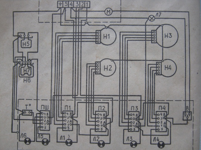
So, the electric stove has four burners; naturally, each of them has its own connection diagram. First two heating elements have indexes h2 and h3. Their main difference is their tubular structure.
The third burner in the electric stove connection diagram has the index H3. It is made of cast iron and is quite large - 200 mm. H4 is also made from cast iron. Its size is 145 mm.
Regulators P1 and P2 are responsible for adjusting the temperature. They do not have power levels as such. But this drawback is more than compensated for by the seven-speed switches P3 and P4. In turn, the PSh is responsible for the oven and has 3 positions.
Switch P5 is responsible for blocking. The signal lamps for the burners in the electric stove circuit are L1-4. The fifth L allows you to illuminate the oven. Also available L6. It turns on when the appropriate temperature is reached in the cabinet.
For heating oven elements H5-6 correspond respectively. Seven is a grill. The thermostat is designated by the simple letter T. There is also a key switch - this is B. The seventh L illuminates the oven.
Attention! The gearmotor is designated as capital letter M.
Schemes for other popular models

Of course, electric stoves Electra 1002 and Dream 8 were one of the most popular in their time. But now people prefer to buy products from completely different brands; among the most famous are Gorenje and Hansa. It is their stoves that most people install in their kitchens.
You can also remember the Lysva brand. Of course, few people now buy their stoves if they have the opportunity to purchase products from a more respectable brand, however, the company has a fairly large circle of consumers. In general, below you will find wiring diagrams for electric stove burners from the most popular brands.

With this diagram for connecting electric stove burners, you can easily do all the work yourself. But for their quality implementation it would not hurt to at least basic knowledge operation of electrical networks and electrical appliances.
The nuances of connecting the heating element and checking it

The heating element provides normal work electric stove burners. In fact, this is its main element, without which the normal functioning of the entire circuit is impossible. But for everything to go smoothly, it is necessary to take into account many nuances. Among the main ones:
- The contact connections should not touch the body of the electric stove, otherwise the connection may end disastrously.
- The contacts must be properly insulated. Cambric is best suited for this purpose. As a last resort, you can use regular electrical tape. But its reliability is much worse.
- It is very important to test the heating element of the electric stove burner so that the connection according to the diagram is successful.
To test the heating element of an electric stove burner you will need a special device. It's called an ohmmeter. A multimeter is also quite suitable for this purpose. These devices are designed to measure resistance in a circuit.
If you are using a multimeter, then first you need to set the appropriate measurement mode. Next, the two wires must be connected to the corresponding sockets.

After this, you need to turn on the device. Using two probes you can measure the resistance of heating elements. To do this, you need to use probes to connect the electric stove burner to the contacts of the heating element.
If your measuring device is a digital multimeter, then after connecting its probes to the contacts, the display will immediately show the result. Three positions are possible:
- gap,
- complete unsuitability
- resistance.
Of course, in order to connect the heating element of the burner to the electric stove according to the diagram, it is necessary for the multimeter to show the third position. Otherwise, nothing will work.
After connecting the heating element of an electric stove, each person has a question: will the burner work after this? Are all wires connected correctly? This is especially true when it comes to burners.
Attention! Diagnostics of the connection of all wires of the heating element to the general circuit of the electric stove should be carried out in a passive state.
For diagnostics you will need the same device. Before testing, the load of the electric stove is turned off, the power switch is turned on and the probes are connected to the plug. The display will show the corresponding result.
Results
It is not difficult to connect the burner and all its elements to the electric stove according to the diagram. It is enough to have the appropriate diagram and basic knowledge of operation electrical network and electric stoves.
bouw.ru
Device diagram and operating principle of the electric stove
Modern city apartments in multi-storey buildings have only electrical wiring, without a gas pipeline, so electric stoves are installed in the kitchen. Many new residents are interested in the principle of operation of an electric stove, as well as its design. In this article we will try to give a comprehensive answer.

Basic equipment
The design of any model of domestic or imported electric stove is almost the same, but they all have their own original nuances. For example, modern Hansa electric stoves from Germany have a special configuration, but we will look at the standard option that every electric stove model has. Traditionally, these products are a combination electrical appliance, intended for cooking, it combines:
- hob with burners;
- oven;
- bottom drawer for storing dishes and baking sheets.
The operating principle is standard for most electrical appliances: current passing through the heating element heats it to a given temperature. For convenient control, there are located on the front front panel regulators- they can be mechanical or electronic, depending on the class of the product. As a rule, on the same panel there are two indicators: one notifies when the device is turned on, and the second notifies when the oven is turned on. Some stoves only have the first indicator. Using the controls, users can set the cooking mode on any burner or oven.
The figure below shows a diagram of a standard electric stove.

Let's decipher the notation:
- power regulator;
- terminal box;
- burner;
- support bar;
- oven temperature sensor;
- a loop;
- stopper;
- oven heating element holder;
- oven heating element;
- internal cladding panel;
- door latch lock;
- latch socket;
- insulating gasket;
- heating element for grilling;
- burner rim;
- power cord;
- ground terminal;
- adjustment knobs.
Types of electric stove surfaces
On modern stage developments in technology, models of electric stoves are divided depending on the type hob into two categories.
Enamel
Classic electric stoves - enameled surface with cast iron burners. The advantages of such a device are obvious:
- low cost;
- simple maintenance and repair.
In addition, the hob coating resistant to mechanical damage from accidental falling of small kitchen utensils and heavy frying pans. Not without its drawbacks:
- long cooking times;
- part of the thermal energy is wasted, especially after turning off the burners, which take a long time to cool down, heating the kitchen air;
- Cleaning the surface takes a lot of time and effort - you need to use special chemicals.

Glass ceramics
Modern electric stoves are equipped with a glass-ceramic surface, which looks very aesthetically pleasing and stylish. What other advantages are there?
- the entire hob is covered with a high-strength ceramic sheet;
- heating occurs only in the hotplate area, which ensures safety of use;
- the smooth surface prevents accidental overturning of the dishes;
- The dimensions of the burners can be up to 60 cm in diameter;
- fast heating and cooling - the heating element operating in intensive mode cools down completely after just a minute;
- easy care - the surface is easy to clean using mild cleaning agents.
The electrical circuit is designed in such a way that when removing dishes from the burner, the automation instantly turns off the heating element.
Control of such plates is usually carried out using touch sensors, which are located on the hob in a fairly convenient place, making them safe to use.

Despite the abundance of advantages, there are also disadvantages:
- You cannot cook in aluminum and copper cookware - they leave unattractive marks on the surface; you can only use stainless steel cookware with a smooth bottom;
- This is a glass surface that is subject to mechanical stress from sharp objects, which are abundant in any kitchen.
Heating elements
The difference between electric stoves may also be in the design of their burners. Let's look at the main types.
Spiral burners
Visually they are very similar to electric kettle heating element- this is an ordinary heating element, which is designed to heat the installed on it kitchen utensils. Such burners come in single and double types - the second option differs in that the second is located around the first spiral. These devices are adjusted using mechanical rotary switches, where continuous adjustment is used.

Pancake option
Such products have continuous surface, which is heated by two or more heaters mounted on metal base. The adjustment is made by special rotary switches that connect the heating element in various combinations. They have several positions, they are called step power regulators - this is how they differ from previous devices for adjusting spiral burners.
To protect products of spiral and pancake type burners, the developers came up with an original device that automatically turns off the heating element if the temperature of the pan has reached such a value that its contents can splash out and flood the surface of the burner.

Halogen type
Heating elements of various configurations are placed under the glass-ceramic hob in any order, as the designers come up with. The dishes are heated by a special halogen emitter: The area indicated by the LED indicator heats up in a few seconds. On such a burner it is good to cook food without prolonged simmering, and energy consumption is no more than 2 kilowatts per hour.
This option requires cookware made of cast iron or steel - this should be taken into account by all users when purchasing such a stove.
Heating adjustment is carried out directly on the top of the hob using touch buttons, lower cost models include standard control using controls located on the front control panel.

Ceramic devices
This type of heating element is similar to a labyrinth in which spiral of nichrome thread - the design of each burner is thought out perfectly so that the spiral heats the maximum area. These products are mounted directly under the glass-ceramic surfaces of the panel where food is prepared; quite often they are used in combination with the halogen version in one stove. To control the heating of these devices, switches with smooth two-stage adjustment are often used.
Oven
The heat inside the cabinet required for preparing various dishes is generated using a special configuration of heating elements, which are specially manufactured using a special technology for use in electric stove ovens. The amount of heating inside is regulated by a switch located on the control panel - a thermostat. Most ovens equipped with a timer, which not only turns off the device at the right time, but can also turn it on if the user installs the necessary program in advance.
Some models have convection - the fan distributes hot air evenly throughout the entire volume of the cabinet, so there is no need to turn, for example, a duck carcass while baking it on a baking sheet.
In the most advanced models, a special coating is applied to the entire surface of the oven. High Quality enamel coating, thanks to which maintaining internal cleanliness is quite simple. For example, the Hans brand has a special mode - pyrolytic cleaning, when turned on, all dripping fat instantly turns into ash.

How does the grill work?
In every modern electric stove There is a device called a grill. To implement this function use several heating elements, the action of which is aimed at ensuring that baking proceeds evenly in different modes. The adjustment is made using a combination of mechanical type regulator located on the control panel.
Electric stoves are considered not only a unique product for high-quality cooking - they can become a highlight of the design of your kitchen interior. Each buyer will find his own model, made in classic or modern style- variety of sizes and color solutions, the presence of a large number functional features allows you to choose an electric stove according to your personal priorities.
tehnika.expert
ELECTRIC STOVE DIAGRAM
Back in the Stone Age, people realized that meat that was fried in the fire was much tastier. raw meat. Since then, people have learned to cook food over fire, gradually adding unique seasonings and new ingredients, and this is how cooking appeared. Centuries and millennia have passed, but the technology has not changed, only the conditions have changed. Now almost every one of us has a stove in our home - gas or electric. An electric stove has its own advantages and features, unlike a gas stove, it is safer, there is less risk of fire and poisoning carbon monoxide. Although it can also lead to a fire if handled carelessly, since it is not visually noticeable whether it is on or not.

The electric stove consists of a work table with 4 burners. Most often, each is done at a certain power, which differs from neighboring burners. The burners have different diameters, very often the burner is a heating element - a heating element. A mesh can be placed on the desktop for ease of use. The power of each burner mainly depends on the specific type.

Cast iron burners are made from alloys of different metals (iron, copper, aluminum), they are usually more powerful (900-1600 watts), spiral-shaped burners (heating elements) are usually made with a power of 400-600 watts.

The electric stove oven has 2 heaters, often in the form of rectangular heating elements. The power of one such heating element is in the region of 1000-1700 watts. The oven heating elements are located in a vertical position. The oven also has a light to monitor the cooking process. On the control panel of the electric stove you can see control knobs, which are designed to control the burners and oven. Next to each knob there may be a built-in indicator that notifies you when a certain burner is turned on. Electric stove diagram:

In older models of electric stoves, the handle simply switches the operating modes of the burner; in modern gas stoves, where digital control is implemented, there is a system for smooth temperature control, and in the latest new products, handles are completely replaced with sensors. The current consumed by an electric stove can reach 20 amperes at full power, and in order to withstand such current, good, powerful contacts of the socket and power plug are required. After installing the electric stove and connecting it to the outlet, it is necessary to check the phase between the “ground” and the zero phase; the ohmmeter readings should be infinity and 4-10 Ohms, respectively. After this, you can apply voltage to the electric stove.
el-shema.ru
DIY electric stove repair. Connecting an electric burner
From practice, it can be observed that connecting electric stoves to an external electrical network, depending on their purpose, service areas, can be with a single-phase connection network \220V\ and a three-phase network with a neutral \380V\, neutral-neutral wire.
In addition to both connection methods, there is a ground wire. In electric stoves and their diagrams you can clearly see that the ground wire is connected to outside housings of electric burners, oven heaters and directly, as in any other equipment, to the body of the electric stove itself. Installation connections electric stoves with single-phase circuits have three connection terminals connected by a jumper on the left side and two connection terminals with a jumper on right side, the sixth terminal is used for grounding. Each terminal of the wiring connection in the diagram is numbered, where you can easily figure out where this or that wire is connected from the wiring connection. We take any diagram of an electric stove and trace the electrical circuit of connections. In the example description there is a diagram of a four-burner electric stove with an electric oven.
The circuit has three connected wires from three mounting terminals of permissible phase potential and two connected wires from two mounting terminals of zero potential. The lead wires from the terminals are connected to the power switches. Power switches come in both stepped and smooth transition versions - they are used to change the resistance.
In this description, each electric burner and oven heaters in general have their own separate power switch. Four wires are connected to each burner from the power switch, why exactly four?, because each electric burner has three incandescent coils and each electric burner spiral has its own resistance. A coil with less resistance will create a temperature with the most heating, a coil with more resistance will create a temperature with the least heating. Power switches act as a potentiometer \the principle of operation of a potentiometer was outlined earlier\, therefore, by changing the resistance both on the power switch itself and on the electric burner itself, you can regulate the heating temperature.
How to fix an electric stove?
In the oven, depending on the modification of the electric stove, there can be either two or four heaters (in everyday life they are called heating elements). The power of the heaters must match the power of the switch itself. If the power switch is incorrectly selected for the oven heaters, gradual burning may occur. contact group in the power switch itself.
In design electric stoves and in the diagrams themselves you can trace the installation of thermostats. Thermoregulators operate on the principle of a thermal relay; when the bimetallic plate is heated to a certain temperature, the plate itself deforms and the contact is disconnected. Here there must be the correct relationship between the thermostat and the heaters of both the oven itself and the individual burners. Incorrect selection can result in prolonged overheating, a break in the electrical circuit and the service life of the electric stove will be insignificant.
A gearmotor can also be installed in electric stoves. Geared motor - electric motor with small rotating magnetic field stator windings, as a result, the rotor rotation speed is low. The mechanical drive is a gearbox that rotates the spit itself.
Signal lamps for turning on and off are in contact with the thermostat to prevent overheating of both the burners themselves and the oven heaters.
What to do if the electric stove breaks down?
(Electric stove Dream, hansa, indesit, combustion, etc.)
In the event of a breakdown of the electric stove, be it with oven or not... - you need to test a separate circuit of the electrical circuit and their connections for resistance with a probe or multimeter, ring each burner, each oven heater, check the serviceability of each lamp.

Testing the electrical circuit must be carried out in a passive way - when the electric stove is not connected to an external power source. When the electric stove is connected to an external source, we can only use the device to measure voltage and current in a particular section of the electrical circuit.
Connecting electric stove burners

It is acceptable for an electric stove GORENIE - E 405 consisting of three burners with the following power:
- two burners of 1500 W each;
- one burner \1200 W\,
The resistance for each burner has the following value:
- at 1500 W \60 ohm - 90 ohm - 60 ohm\;
- at 1200 W \130 ohm - 90 ohm - 60 ohm\.
This diagram shows the connection of the contact connections of the burners with contact connections switch. Depending on the connection of one or another burner resistance, the heating temperature of the burner will correspond.
zapiski-elektrika.ru
Electrical diagram of the Tom-M electric stove. Tom-M electric furnace diagram
Electrical diagram of the Tom-M electric stove. Tom-M electric furnace diagram
The Tom-M electric stove has a fairly simple electrical circuit, consisting of simple basic elements, and
namely, it includes: signal lamps - four pieces, resistances - four pieces,
five switches - three for the burners and two for the frying electric cabinet, backlight, backlight switch
one, two heating elements and three burners. Below is electrical diagram connections for the Tom-M stove, which has modes
The operation of the electric frying cabinet is regulated using two switches! The following are used in the electric furnace diagram:
symbols: SL - signal light, R - resistance (resistor), P - switch, LP - designation
backlight lamps, KP - oven lighting key, numbers 1, 2 and 3 - burners.
Electrical diagram of the Tom-M stove - Technical data of the stove and its components.
The installed power of the electric furnace is 6 kW, the one-time power consumption of the furnace is 4.5 kW,
maximum current - 20.4 A, rated voltage 220V single-phase alternating current. Middle burner (diameter 145
mm) - heater type EKCH-145-1/220, near right burner (diameter 180 mm) - heater type EKCH-180-1.5/220,
far left burner (diameter 180 mm) - heater type EKCH-180-1.5/220, electric oven oven heaters
type TEN-170-4-1/1S220.
Electrical diagram of the Tom-M furnace - Heater powers at the corresponding handle positions
switches.
Middle burner: “1” — 0.103 kW, “2” — 0.133 kW, “3” — 0.225 kW, “4” — 0.45 kW, “5” — 0.675 kW, “6” —
1 kW. Near right burner: “1” — 0.148 kW, “2” — 0.21 kW, “3” — 0.3 kW, “4” — 0.7 kW, “5” — 1 kW, “6” —
1.5 kW. Far left burner: "1" - 0.148 kW, "2" - 0.21 kW, "3" - 0.3 kW, "4" - 0.7 kW, "5" - 1 kW, "6" —
1.5 kW. Electric stove cabinet heaters Tom-M: “1” - 0.5 kW, “2” - 1 kW, “3” - 1 kW, “4” - 2 kW.
Dependence of the oven temperature of the Tom-M electric furnace on the switching stage.
The stove cabinet switch is turned to position “4” (heating elements are connected in parallel) - up to 300 degrees Celsius,
the switch is turned on to position “3” (the lower heating element is turned on) - 225 - 260 degrees Celsius, the switch is in
position “2” (upper heating element is on) – 180 – 220 degrees Celsius, power switch is turned to position “1” (heating element
included in series) - 110 - 130 degrees Celsius.

VINEGRET.RU - A little bit about everything. HOME
kak-varit-ris.ru
Connecting an electric stove burner
Not in all areas gas is supplied to residential buildings. In such situations, you have to make do with electric stoves. The old models are still in use. Sometimes unpleasant situations occur with them that require the replacement of certain elements. A burner connection diagram would be useful, since it is often the heating elements that fail and require replacement.
Common models
Heating elements for old tiles are not supposed to break, but they still do. This may be due to the fact that the tile heater for a long time runs idle after someone forgot to turn it off, or there is a sudden power surge that affects the burner. If mechanical damage in the form of cracks is visible on the surface of the heating element, then we can say for sure that it was heated to very high temperatures. high temperatures. Initially, the connection diagram is in the product passport. If its condition is satisfactory, it is easy to clarify, but most often such documents are lost or have already been thrown away, then you can use the guidance that will be given in the article.
Electra
Electra is one of those stoves that were installed in new buildings or purchased independently. We are talking about a stove with model number 1002. The circuit that was developed by the designers for connection is not particularly complicated, so even a person far from electricity can figure it out. There are four heating elements on the top of the stove. Each of them is designated by a number from 1 to 4 and has the letter index “H”. The first two burners of the stove are heating elements, i.e. tubular heaters. The element under serial number 3 is made of cast iron and has large diameter 20 cm. The fourth element is made similar to the third, but its diameter is slightly smaller and is 14 cm.
Each burner on the stove has its own switch. They also have a numerical designation, but the first two are prefixed with the letter “P”, and the third and fourth are prefixed with the letter “P”. The latter have the advantage of adjusting the power in seven stages, which allows you to select the desired mode. The stove oven has a separate regulator with three positions. It is designated by the abbreviation “ПШ”. The indicator lamps in the diagram are designated by the letter “L” and a serial number from 1 to 4, which also corresponds to the burner number. The oven also has its own lamp, which is designated by the number 5. The oven contains two more heating elements, which are designated by the numbers 5 and 6 with the corresponding letter. The seventh heater is located at the top of the oven and is a grill.
Replacing any heating element involves first removing it from the tile. To do this, you will have to remove the protective caps and strips. During disassembly, you can trace where the conductors from a particular heater go in the stove. If the wires have melted, then you can clarify this point using the diagram given above. It also shows how to connect the power line. The new heater is simply installed in the stove, fixed and connected.
Dream
Even more popular than Electra was the Dream stove with model number 8. It is a small oven with two heating elements on the top edge. In the diagrams for this stove, the heaters that are located on the burners are designated by numbers 1 and 2, next to them is the letter index “E”. Heaters 3 to 5 are located inside the oven. The main module, thanks to which the settings are performed, is designated by numbers 1 to 4 and has the index S. The design includes light indicators. They could signal the operation of the burners, heating elements inside the oven, and simply the backlight. In the passport they are designated as HL and have numbers from 1 to 3.
Note! In the diagram you can also find an element designated T-300. This is a thermal relay that was responsible for shutting down when a certain temperature was reached.
The stove has the ability to control the heating intensity. It is produced by switch S1. Thanks to contact closure electricity comes from the plug, which is marked XP and through fuse F is supplied to the heater, which is located in the oven. It is connected in series with the rest of the heating elements that are in the oven. This means that before replacing, it is necessary to determine which specific heater has failed. This can be done by changing the position of the switch so that power is supplied separately to one or two heaters in the oven. Each burner also has its own switch. The diagram shows how the wires go to connect each individual heater.
Lysva
Another manufacturer that was quite common in the past is Lysva. For example, below is a diagram that will allow you to replace a burner on a stove that has three main heaters and those in the oven. Each heater on the burner has 6 adjustment modes. The task is performed by increasing or decreasing the resistance of the conductors. The diagram shows the installed resistors. Three of them go to each heating element and four more to the oven. Based on how the current flows through the circuit, you can easily install a new heater. At the end of the article there will be a video about connecting a burner with four terminals.
Before you start replacing an element on the stove, you need to make sure whether it is really out of order. It is almost impossible to do this with a regular dial, since the heating element has its own resistance. It is the resistance that needs to be checked. The manufacturer indicates what value is normal for a working unit. It is necessary to attach two multimeter probes to the heater contacts and switch to resistance measurement mode. At the end of the process, you need to check the reference value.
Note! The resistance must be measured on a dismantled heater, otherwise the value of the entire system will be displayed.
During installation, be careful at the connection points. All exposed wires must be insulated with electrical tape or heat shrink tube. No exposed wire should touch the stove body. When performing replacement work, it is necessary to turn off the power to the stove. All tools that will be used must have dielectric handles that will not allow the discharge that may occur in the capacitors, if they are present in the circuit.
Conclusion
As you can see, having a diagram, replacing the heater is not so difficult. You should never rush to disconnect any wires. It’s better to start by photographing them with your smartphone or digital camera to know how to connect in reverse order.
2proraba.com
principle of operation, electrical circuit, how the oven works
Even in big cities, not to mention small villages, there are residential buildings where there is no gas main. But there is hardly a building that does not have electricity. And in such conditions, only an electric stove can successfully replace the usual gas counterpart. The basic structure and principle of operation of electric stoves are further in the material.
Basic design and operating principle
Nowadays renovation household appliances often costs the amount for which, if you pay a little extra, you can buy a new similar thing. Therefore, it is not surprising that the average user strives to independently diagnose and eliminate malfunctions that inevitably arise during the operation of any equipment. And for this he needs to understand how the electric stove works.

Standard the oven consists from:
- hob on which burners and power controls are located;
- built-in oven, often equipped with a grill;
- lower compartment, which is used for storing grates and baking sheets, and its real purpose is in the air gap that protects flooring from the heat of the oven.
Important! The basic design of an electric stove is identical for all manufacturers. The difference can only be in the configuration and functionality.
Common for all slabs electrical diagram implies that current flowing to the heating element heats it to a certain temperature. And the already heated heating element gives off its heat to the dishes and everything that surrounds it. Only an induction furnace does not heat up the surrounding area, but it has a different operating principle.

Types and arrangement of cooking surfaces
One of distinctive features The arrangement of the surface of an electric stove from a gas stove is to place the dishes not on the grate, but directly on the burners or simply on hob. The top of the electric stove can be made of the following materials:
- steel sheet coated with enamel;
- ceramics;
- glass ceramics.
Enameled surface It has external cast iron burners and is characterized by a long cooling time after completion of work. It is highly resistant to mechanical and chemical properties. Disadvantage steel structure This results in inefficient heat consumption: both the stove itself and all the surrounding air are heated in vain.

Surfaces made made of ceramics and glass ceramics, are strong enough to withstand impact. But they are easily damaged by scratching or chemical reactions. For example, regular sugar, when melted on the stove, leaves a stain that cannot be removed. But this is also where the strength of the material decreases.

Otherwise, such surfaces have numerous advantages, one of which is hidden under the burner sheet. This allows the use in the furnace design Various types heaters and even install different types of them at the same time, which allows you to optimize the cooking process.
In stoves with ceramic and glass-ceramic surfaces, the quality of energy saving is perfectly realized: as soon as you remove the dishes from the area where the heater is operating, the heating element automatically turns off. Cleaning of such a panel is kept to a minimum - just wipe the entire surface with a damp cloth, because there is no place for dirt and debris to accumulate. However significant disadvantage is that the surface temperature in both options during operation is very high.

Important! Carelessness during cooking can result in burns.
Types and design of heating elements
Electric stoves made according to one standard design differ in a variety of heating elements. Four of their types, which are described in detail below, have become widespread.
Spiral burners
Today, this type of heating elements is becoming a thing of the past. They are most often used in tabletop models - with one or two burners. An example is the Dream electric stove (112T, 211T, 212T). Spiral burners use ordinary heating elements open type like in an electric kettle. They are single or double. Power control is usually mechanical and smooth.

Pancake burners
This is the most common type of burner, which involves placement of two heating elements in a solid cast iron body. Some models may have more heaters inside. For adjustment, a mechanical step switch is usually used, each position of which connects a new combination of heating elements to create the required power. Among domestic models, such burners are used in Electra 1001m and Lysva. Among Western manufacturers, they are found in Electrolux and Indesit.

Halogen burners
The principle of operation of such burners is that The halogen heating element emits heat, which heats up a specific area of the glass-ceramic sheet panel., illuminated by an LED indicator. In such models, heating occurs very quickly: in just a few seconds, the maximum value of the set temperature is reached under the pan.
This type of burner involves touch-sensitive power control. But some budget models have adjustment knobs. Energy consumption of halogen heating elements is no more than 2 kW/h. They can be seen in BEKO models, for example in the CSE 57300 GS example.

Ceramic burners
With such a heater nichrome thread in the form of a spiral lies in special grooves cut into a ceramic stand. The grooves are like a labyrinth, and the laying is done in such a way as to cover as much as possible large area for efficient heating. This heating element is located under the glass-ceramic sheet. If you need to replace the burner switch, you should look for two-stage ones with smooth adjustment. These are the ones that are most suitable this type heaters.

Ceramic burners are used by almost all manufacturers producing similar products. IN modern ovens Along with ceramic heating elements, you can often see halogen devices(for example, models from the Gefest and Gorenje brands).
Types of ovens
To create and maintain the temperature necessary for cooking in the oven, special heating elements were developed. Their production is carried out using a special technology, which uses a specific configuration to produce the required heat indicators. Structurally ovens differ in the type of heating elements used. They vary in configuration and dimensions, in power, in design (double- and single-circuit), as well as in purpose (top, bottom, side, grill).
But in addition to the main task (roasting), many ovens are equipped additional, no less useful, functions. Important role The presence or absence of built-in cleaning methods plays a role in the operation of the oven. Modern models They have several of them to choose from.

Many ovens have a convention that promotes uniform baking of the product. It happens that a steam generating generator is installed, and then the oven can perform the functions of a steamer. Sometimes the device operates in microwave mode.

But very often together with the oven install the grill. It is located at the top of the chamber. Often, a halogen heating element is used for these purposes. infrared lamp. To create a golden brown crust, the product is placed in close proximity to a powerful heater. And to distribute the heat evenly over the entire surface, an electric spit is used.

Today's electric stoves are equipped with timers, lighting elements, clocks and displays. Many have the ability to use cooking programs and, importantly, child lock. So, electric ovens become a worthy alternative classic gas stoves in homes where there is no gas supply. They do an excellent job of cooking, and the reduced electricity tariff in such houses allows you to use all the useful functions without the need to save.
Reading time ≈ 3 minutes
When carrying out work on the electrical network, always turn off the power. Typically, the latest modifications of electric stoves are sold without a connecting cord. The electric stove must be connected using high-quality terminals. Moreover, a socketless connection is used. With this connection, it is possible to use longer wires with fuses. True, sometimes you can use an outlet. It is important that the current of such an outlet is at least 32 Amperes.
Connecting an electric stove yourself is also permissible, but you should keep in mind that the diameter of the wires in the cable is at least 4 mm. If the cable length exceeds 12 meters, then the diameter of the copper core must be at least 6 mm. Moreover, the cable must be protected by an independent automatic fuse.
Electric stove connection diagram
The connection diagram for an electric stove of this type is called radial. There is also a ring scheme. With this connection scheme, several sockets can be placed on one cable. It is prohibited to connect multiple electrical appliances through the bug.

To answer the question of how to connect an electric stove with your own hands, you should know how many connection diagrams there are. Moreover, connecting a built-in electric stove is no different from connecting a stand-alone stove. Available in single-phase, two-phase and three phase system connecting the electric stove. Since a single-phase system is common in our apartments, the stove should be connected using a single-phase circuit. For this purpose, appropriate jumpers are installed in the terminal block. Then you should connect to the block power cable. The socket must be installed in the location you choose so that the cable length is sufficient.

Special attention When connecting an electric stove, attention should be paid to connecting the burners. The connection diagram for the burners can be found in the data sheet that is included with the purchase of the electric stove. Typically, a burner includes a steel housing, a terminal block, thermal insulation and flat-type heaters.

The heating element is installed in a cell of the appropriate size. The surface of the burner should be higher than the surface of the stove itself. There are special screws that regulate the horizontal position of the heating elements. The cable cores are connected to the screws and clamped with appropriate nuts. Connecting a burner is a rather labor-intensive and responsible process. When incorrect installation heating elements can damage the stove.

After you have installed the burners in the electric stove, you should check whether the connection in the electrical panel is made correctly. Only after this should you connect the stove and check its operation in test mode. Moreover, it is important to check in this mode all the options that are provided in the instructions. Based on many years of experience in operating electric stoves, it can be argued that when correct connection The tile will serve reliably and for a long time. If you are not entirely confident in your abilities, then it is better to use the services of specialists.
Modern city apartments in multi-storey buildings have only electrical wiring, no gas pipeline, so in the kitchen. Many new residents are interested in the principle of operation of an electric stove, as well as its design. In this article we will try to give a comprehensive answer.
The design of any model of domestic or imported electric stove is almost the same, but they all have their own original nuances. For example, modern Hansa electric stoves from Germany have a special configuration, but we will look at the standard option that every electric stove model has. Traditionally, these products are a combined electrical appliance designed for cooking; it combines:
- hob with burners;
- oven;
- bottom drawer for storing dishes and baking sheets.
The operating principle is standard for most electrical appliances: current passing through the heating element heats it to a given temperature. For convenient control, there are located on the front front panel regulators- they can be mechanical or electronic, depending on the class of the product. As a rule, on the same panel there are two indicators: one notifies when the device is turned on, and the second notifies when the oven is turned on. Some stoves only have the first indicator. Using the controls, users can set the cooking mode on any burner or oven.
The figure below shows a diagram of a standard electric stove.

Let's decipher the notation:
- power regulator;
- terminal box;
- burner;
- support bar;
- oven temperature sensor;
- a loop;
- stopper;
- oven heating element holder;
- oven heating element;
- internal cladding panel;
- door latch lock;
- latch socket;
- insulating gasket;
- heating element for grilling;
- burner rim;
- power cord;
- ground terminal;
- adjustment knobs.
Types of electric stove surfaces
At the present stage of technological development, models of electric stoves are divided into two categories depending on the type of hob.
Enamel
Classic electric stoves - enameled surface with cast iron burners. The advantages of such a device are obvious:
- low cost;
- simple maintenance and repair.
In addition, the hob coating resistant to mechanical damage from accidental falling of small kitchen utensils and heavy pans. Not without its drawbacks:
- long cooking times;
- part of the thermal energy is wasted, especially after turning off the burners, which take a long time to cool down, heating the kitchen air;
- Cleaning the surface takes a lot of time and effort - you need to use special chemicals.

Modern electric stoves are equipped with a glass-ceramic surface, which looks very aesthetically pleasing and stylish. What other advantages are there?
- the entire hob is covered with a high-strength ceramic sheet;
- heating occurs only in the hotplate area, which ensures safety of use;
- the smooth surface prevents accidental overturning of the dishes;
- The dimensions of the burners can be up to 60 cm in diameter;
- fast heating and cooling - the heating element operating in intensive mode cools down completely after just a minute;
- - the surface is easy to clean using mild cleaning agents.
The electrical circuit is designed in such a way that when removing dishes from the burner, the automation instantly turns off the heating element.
Control of such plates is usually carried out using touch sensors, which are located on the hob in a fairly convenient place, making them safe to use.

Despite the abundance of advantages, there are also disadvantages:
- You cannot cook in aluminum and copper cookware - they leave unattractive marks on the surface; you can only use stainless steel cookware with a smooth bottom;
- This is a glass surface that is subject to mechanical stress from sharp objects, which are abundant in any kitchen.
Heating elements
The difference between electric stoves may also be in the design of their burners. Let's look at the main types.
Spiral burners
Visually they are very similar to electric kettle heating element- this is an ordinary heating element, which is designed to heat kitchen utensils installed on it. Such burners come in single and double types - the second option differs in that the second is located around the first spiral. These devices are adjusted using mechanical rotary switches, where continuous adjustment is used.

Pancake option
Such products have continuous surface, which is heated by two or more heaters mounted on a metal base. The adjustment is made by special rotary switches that connect the heating element in various combinations. They have several positions, they are called step power regulators - this is how they differ from previous devices for adjusting spiral burners.
To protect products of spiral and pancake type burners, the developers came up with an original device that automatically turns off the heating element if the temperature of the pan has reached such a value that its contents can splash out and flood the surface of the burner.

Halogen type
Heating elements of various configurations are placed under the glass-ceramic hob in any order, as the designers come up with. The dishes are heated by a special halogen emitter: The area indicated by the LED indicator heats up in a few seconds. On such a burner it is good to cook food without prolonged simmering, and energy consumption is no more than 2 kilowatts per hour.
This option requires cookware made of cast iron or steel - this should be taken into account by all users when purchasing such a stove.
Heating adjustment is carried out directly on the top of the hob using touch buttons, lower cost models include standard control using controls located on the front control panel.

Ceramic devices
This type of heating element is similar to a labyrinth in which spiral made of nichrome thread- the design of each burner is thought out perfectly so that the spiral heats the maximum area. These products are mounted directly under the glass-ceramic surfaces of the panel where food is prepared; quite often they are used in combination with the halogen version in one stove. To control the heating of these devices, switches with smooth two-stage adjustment are often used.

Oven
The heat inside the cabinet required for preparing various dishes is generated using a special configuration of heating elements, which are specially manufactured using a special technology for use in electric stove ovens. The amount of heating inside is regulated by a switch located on the control panel - a thermostat. Most ovens equipped with a timer, which not only turns off the device at the right time, but can also turn it on if the user installs the necessary program in advance.
Some models have a fan that distributes hot air evenly throughout the entire volume of the cabinet, so there is no need to turn, for example, a duck carcass while it is baking on a baking sheet.
The entire surface of the oven in the most advanced models is coated with a special high-quality enamel coating, thanks to which maintaining internal cleanliness is quite simple. For example, the Hans brand has a special mode - when turned on, all dripping fat instantly turns into ash.

How does the grill work?
Every modern electric stove has a device called a grill. To implement this function use several heating elements, the action of which is aimed at ensuring that baking proceeds evenly in different modes. The adjustment is made by a combined mechanical type regulator located on the control panel.
Electric stoves are considered not only a unique product for high-quality cooking - they can become the highlight of your kitchen interior design. Each buyer will find his own model, made in a classic or modern style - a variety of dimensions and colors, the presence of a large number of functional features allows according to personal priorities.
People who have electric stoves that have served for decades are often interested in connection diagrams for the burners. This is not surprising, because over time these elements fail, and the only way to fix everything is to install new burners.
In theory, under ideal operating conditions, burners can last almost forever, but this, of course, does not happen. The fact is that we often forget to turn them off, which causes the heating elements to heat up to unimaginable temperatures. In some cases, you can even see cracks on the surface of burnt-out burners. But this only applies to older models; this does not happen with new ones.
When a stove burner burns out, the owner has to think about connecting a new element. It goes without saying that you can’t do without a diagram. Of course, it should be in the technical data sheet of the product. But we must admit that after 20 years, documents are lost or become unreadable.
Attention ! Ideally, you should connect the new burner to the electric stove exactly according to the diagram indicated in the technical data sheet.
Connection diagrams for popular stoves
Dream 8

This is one of the best selling slabs of the past. It’s not surprising that you can see it in many people’s kitchens. It consists of the following key nodes:
- Heating element E1+ E2,
- Heating element E3-E5,
- S1-S4,
- indicators.
Heating elements E1-2 are located in burners 1 and 2, respectively. This can be easily seen in the diagram in the technical documentation of the stove. TEN E3-E5 is an oven. S1-S4 are a switching unit with which you can control the electric stove.
The indicators available in the electric stove, according to the diagram, are of two types HL1 and HL. They are responsible for the operation of heating elements. Also available HL3. But this is just illumination of the oven, so that you can always see the condition of the dish.
Attention ! Most designs use a T-300 thermal relay. Moreover, the power of each heating element is 1 kW.
Switch S1 is responsible for adjusting the degree of heating. It has four positions with which you can provide different intensity of fire. In the first position, P1-2 and P2-3 are closed.
When this happens, heating element E3 is activated. In this case, the current will travel the following route:
- it all starts with contact XP,
- then comes relay F,
- P1-2,
- E4-5 + E3,
- P2-3.
The first destination is the plug pin. This heating element is connected in series to the fourth heating element and to the fifth. Moreover, it is connected in parallel to the second and third. You can easily verify all this for yourself by looking at the diagram below.

When switching to position number two occurs, P1-1 and P2-3 are activated. Naturally, the circuit through which the current passes changes. It all starts with the plug contact located at the bottom, which is labeled as XP. Then the following intermediate points follow:
- P1-1,
- P2-3.
It all ends with the XP plug on top. When this circuit is activated, exclusively heating element E3 is started. An increase in power can be achieved by reducing resistance. The main advantage of this scheme for connecting an electric stove burner is that it is possible with a constant mains voltage, which is 220 V.
For S1 there is position number 3. In this case, P1-1 and P2-2 are closed. Because of this, the E4+5 heating elements are connected. If we talk about S4, then this switch is responsible for the operation of the lamp. On the standard diagram of the operation of electric stove burners, it is designated HL3.
Electra 1002
The second, most frequently used electric stove in homes and apartments is Electra 1002. Therefore, knowing about its burner connection diagram is simply necessary. Fortunately, it is not particularly difficult and even a beginner can figure it out.
So, the electric stove has four burners; naturally, each of them has its own connection diagram. The first two heating elements are indexed H1 and H2. Their main difference is their tubular structure.
The third burner in the electric stove connection diagram has the index H3. It is made of cast iron and is quite large - 200 mm. H4 is also made from cast iron. Its size is 145 mm.
Regulators P1 and P2 are responsible for adjusting the temperature. They do not have power levels as such. But this drawback is more than compensated for by the seven-speed switches P3 and P4. In turn, the PSh is responsible for the oven and has 3 positions.
Switch P5 is responsible for blocking. The signal lamps for the burners in the electric stove circuit are L1-4. The fifth L allows you to illuminate the oven. Also available L6. It turns on when the appropriate temperature is reached in the cabinet.
Elements H5-6 are respectively responsible for heating the oven. Seven is a grill. The thermostat is designated by the simple letter T. There is also a key switch - this is B. The seventh L illuminates the oven.
Attention ! The gearmotor is designated as a capital letter M.
Schemes for other popular models

Of course, electric stoves Electra 1002 and Dream 8 were one of the most popular in their time. But now people prefer to buy products from completely different brands; among the most famous are Gorenje and Hansa. It is their stoves that most people install in their kitchens.
You can also remember the Lysva brand. Of course, few people now buy their stoves if they have the opportunity to purchase products from a more respectable brand, however, the company has a fairly large circle of consumers. In general, below you will find wiring diagrams for electric stove burners from the most popular brands.

With this diagram for connecting electric stove burners, you can easily do all the work yourself. But for their high-quality implementation, at least basic knowledge of the operation of electrical networks and electrical appliances will not interfere.
The nuances of connecting the heating element and checking it

The heating element ensures normal operation of the electric stove burner. In fact, this is its main element, without which the normal functioning of the entire circuit is impossible. But for everything to go smoothly, it is necessary to take into account many nuances. Among the main ones:
- The contact connections should not touch the body of the electric stove, otherwise the connection may end disastrously.
- The contacts must be properly insulated. Cambric is best suited for this purpose. As a last resort, you can use regular electrical tape. But its reliability is much worse.
- It is very important to test the heating element of the electric stove burner so that the connection according to the diagram is successful.
To test the heating element of an electric stove burner you will need a special device. It's called an ohmmeter. A multimeter is also quite suitable for this purpose. These devices are designed to measure resistance in a circuit.
If you are using a multimeter, then first you need to set the appropriate measurement mode. Next, the two wires must be connected to the corresponding sockets.

After this, you need to turn on the device. Using two probes you can measure the resistance of heating elements. To do this, you need to use probes to connect the electric stove burner to the contacts of the heating element.
If your measuring device is a digital multimeter, then after connecting its probes to the contacts, the display will immediately show the result. Three positions are possible:
- gap,
- complete unsuitability
- resistance.
Of course, in order to connect the heating element of the burner to the electric stove according to the diagram, it is necessary for the multimeter to show the third position. Otherwise, nothing will work.
After connecting the heating element of an electric stove, each person has a question: will the burner work after this? Are all wires connected correctly? This is especially true when it comes to burners.
Attention ! Diagnostics of the connection of all wires of the heating element to the general circuit of the electric stove should be carried out in a passive state.
For diagnostics you will need the same device. Before testing, the load of the electric stove is turned off, the power switch is turned on and the probes are connected to the plug. The display will show the corresponding result.
Results
It is not difficult to connect the burner and all its elements to the electric stove according to the diagram. It is enough to have an appropriate diagram and basic knowledge of the functioning of the electrical network and electric stove.
Every year, more and more people decide to connect an electric stove. This is not surprising. Modern technologies, used in their creation, allow you to achieve considerable savings.
Let's imagine that you have already purchased an electric stove and you need to connect it. In this case, you must first carefully read the instructions. This is where the working connection diagram is indicated.
Attention ! Electric stoves consume large volume electrical energy In comparison with others household appliances, and this must be taken into account when connecting according to the diagram.
Connection algorithm
Before proceeding to directly connecting the electric stove according to the diagram, you need to familiarize yourself with a number of documents:
- PUE 7,
- PTEEP,
- technical certificate.
Only then will you be able to use these instructions correctly. Otherwise, you risk not only losing the warranty on the electric stove, but also putting yourself in danger.
Step 1. Select wires
The power wire according to the diagram must be independent. Simply put, it must be fed directly into the distribution panel. Otherwise, the wiring may simply burn out, thus causing a fire.
If you do not have a dedicated line in your home, then you can use the following types of wires:
- VVG-ng,
- SHVVP.
In turn, in order to connect the electric stove from the outlet according to the diagram, you need to use a PVA type cable. If you can't find it, then KG will do. By the way, the latter has much greater resistance to fractures. During operation, it can bend many times. There will be no harm from this.
When you select the cable cross-section for connecting an electric stove, you need to take into account three main parameters:
- number of phases,
- mains voltage,
- power consumption.
Just look at the table below and select the cable suitable for connecting the electric stove according to the diagram. In this case, it is better to provide a small power reserve, since fluctuations in the network are a common occurrence.

Also, when connecting an electric stove using a do-it-yourself circuit, you need to know about some nuances. Firstly, all operations must be carried out regardless of circuit breaker. Secondly, the current supply rating must be one unit higher than the device consumption.
You can find the technical characteristics of the electric stove in the relevant documentation, which should come with the device in the delivery kit. Also, all parameters are indicated on the case.
Attention ! The circuit breaker must belong to group C.
When connecting an electric stove according to the diagram, you must take care of the presence of an RCD. It will protect you and your family from electric shock during operation of the device.
The RCD must be installed near the circuit breaker. Connecting the device protective shutdown only possible after installing a circuit breaker. Pay special attention to screw terminals. They must be securely fixed.
Step 2. Making a socket

Ideally, you should already have an outlet in your kitchen through which you can connect the electric stove according to the diagram. But unfortunately, not all apartments are equipped with connectors of the required power, so sometimes you have to take care of this yourself.
Attention ! You need an outlet that can provide power to electrical equipment with a power of over 3 kW.
In most cases, a single-phase socket is installed in the kitchen. It is more than enough to connect the electric stove according to the standard circuit. In this case, the minimum rated current must be no less than 32 A. Ideally you need 40.
The socket that you will use to connect the electric stove according to the diagram must be made with quality materials. Electrical contact must also be ensured.
It is very important that the number of cores is the same as the number of wires. Under no circumstances should wires be connected together so that they become possible connection to one contact. This may lead to a fire hazard.
When connecting, you may only use copper wire. In this case, the cross-section of the wire must correspond to the table values. The outlet itself must be installed on a flat surface. However, there should be no highly flammable materials nearby.
Advice ! When installed on brick wall It is advisable to use a gasket to prevent the base of the socket from cracking.

You cannot install a socket for connecting an electric stove according to the diagram near the washbasin. This does not comply with safety regulations. Splashes can get on the exposed cable and cause a short circuit.
Also, the socket should not be installed too close to iron pipes. The same applies to doors and window openings. From the right choice installation location depends safe operation device.
When you finish installing the socket for connecting the electric stove according to the diagram, check the insulation. The cables must not be damaged. Only then turn on the stove.
Attention ! Ideally, the colors of the wires in the plug should match the colors of the cables in the socket.
Pay special attention to the screw terminals, they must be secured properly. Moreover, when installing an outlet, you need every multi-core cable solder additionally. Soldering must be done where they are attached to the contacts.
A multimeter will help you check how correctly you have connected the wires. Once the preliminary check is completed, the circuit breaker can be turned on.
Step 3. Connecting to the stove

To connect the electric stove to the power cable, you will, of course, need a circuit diagram. The exact connection drawing must be in the technical data sheet. Once you find it, you will need to find the small cover on the back panel and unscrew it. Underneath you will find the wire terminals.
Now you can secure the wires to connect the electric stove according to the diagram. But before that, you need to secure all the cables. Otherwise, with a careless movement you will simply tear them out.
Attention ! There are special clamps for fastening on the body of the electric stove.
The connection of wires depends on the number of phases. For pairing you need to use copper jumpers. They usually come with the terminal block. Make connections according to the diagram you have. After this, tighten the screws.
Usually in the documentation or on the cover itself there is a diagram with which you can connect the stove. Wherein The colors of the connected cables should ideally match each other.
First of all, you need to connect the ground. Usually this wire has light green color(a mixture of yellow and green). After this you can connect the neutral. The blue cable is connected third. Only after this can you move on to the phase wires. The sequence is as follows:
- brown,
- black,
- black.
Extreme caution must be maintained during the connection process, as incorrect contact can lead to failure of the plate or wiring. At the end of the work the lid is closed.
General network connection diagrams

Perhaps this is the most simple circuit connection to a single-phase network, in order to connect the power you will need:
- Install jumpers on terminals L1 and L2, L2 and L3.
- Connect the brown wire under the phase to L2.
- Install a jumper on N1 and N2.
- Connect neutral to N2.
- The grounding wire is connected to the grounding contact.
However, you must remember that this general scheme. Many diagrams that come with the documentation may have different terminal names.. Moreover, even their number may be different.
If you need to connect the stove to three-phase network, then the scheme will be slightly different. You will have three phases that you simply need to connect to the three terminals L1-L3. In this case, no jumpers are needed during the installation process. N1 and N2 together with PE are connected to the advisory contacts.
With a two-phase network, you will need to install a jumper on L1 and L2. After this, you can connect phase A to them. Accordingly, L3 will output to C. All other wires can be connected in the same way as previous networks.
Results
Connecting an electric stove to the network is not so difficult. Moreover, this is possible in apartments and houses where the design did not provide sockets of this type. But to make this possible, it is necessary to use high-quality components and take into account important nuances like the number of phases in the network.