Length of nichrome wire for spiral winding. Calculation of a wire heater for an electric furnace
You will need
- Spiral, caliper, ruler. It is necessary to know the material of the spiral, the current strength I and voltage U at which the spiral will operate, and what material it is made of.
Instructions
Find out what resistance R your coil should have. To do this, use Ohm's law and substitute the value of the current I in the circuit and the voltage U at the ends of the spiral into the formula R=U/I.
Using the reference book, determine the specific electrical resistance material ρ from which the spiral will be made. ρ must be expressed in Ohm m. If the value of ρ in the reference book is given in Ohm mm²/m, then multiply it by 0.000001. For example: resistivity copper ρ=0.0175 Ohm mm²/m, when converted to SI we have ρ=0.0175 0.000001=0.0000000175 Ohm m.
Find the length of the wire using the formula: Lₒ=R S/ρ.
Measure an arbitrary length l with a ruler on the spiral (for example: l=10cm=0.1m). Count the number of turns n coming to this length. Determine the spiral pitch H=l/n or measure it with a caliper.
Find how many turns N can be made from wire of length Lₒ: N= Lₒ/(πD+H).
Find the length of the spiral itself using the formula: L=Lₒ/N.
A spiral scarf is also called a boa scarf or a wave scarf. The main thing here is not the type of yarn, not the knitting pattern or color. finished product, but the execution technique and originality of the model. The spiral scarf represents festivity, splendor, and solemnity. It looks like an elegant lace frill, an exotic boa, and an ordinary, but very original scarf.
How to knit a spiral scarf with knitting needles
To knit a spiral scarf, cast on 24 stitches and knit the 1st row:
- 1 edge loop;
- 11 facial;
- 12 purl loops.
The quality and color of the yarn for this spiral scarf model is at your discretion.
1st row: first 1 edge loop, then 1 yarn over, then 1 knit stitch, then 1 yarn over and 8 knit loops. Slip one onto the right needle as a purl, and pull the thread forward between the needles. Return the removed loop to the left knitting needle, pull the thread back between the knitting needles (in this case, the loop will turn out to be wrapped in thread). Turn the work and knit 12 purl stitches.
2nd row: first knit 1 edge loop, then 1 yarn over, then knit 3 knit stitches, 1 yarn over and 6 knit stitches. Slip one onto the right needle as a purl, and pull the thread forward between the needles. Next, return the stitch to the left needle, pull the yarn back between the needles, then turn the work and purl 12 stitches.
3rd row: knit 1 edge loop, then 2 knit stitches together, then knit 1 stitch, then 2 knit stitches together and 4 knit stitches. Slip one onto the right needle as a purl, pull the yarn forward between the needles, return the stitch to the left needle, then pull the yarn back between the needles. After this, turn the work and knit 8 purl stitches.
4th row: knit 1 edge stitch, then knit 3 stitches together, then knit 4 stitches, *take out the wrapped loop from below and knit together with the next knit stitch, knit 1* (repeat * to * 3 times). Without turning the work over, knit the purl stitches.
In this way, knit a spiral scarf to the required length in blocks of these 4 rows.
Almost all women face the issue of contraception. One of the reliable and proven methods is the intrauterine device, which is still in demand today.

Types of spirals
Intrauterine devices are made of plastic and come in two types: copper (silver)-containing devices and hormone-containing devices. Their size is 3X4 cm. The choice of contraceptive method and the device itself occurs at an appointment with a gynecologist. You shouldn't do this yourself. The intrauterine device is installed by a gynecologist during menstruation. It is small in size and resembles the letter T in shape.
A copper spiral is made from copper wire. Its peculiarity is the ability to act on the uterus in such a way that the egg cannot attach to it. This is facilitated by two copper antennae.
The hormonal IUD has a container that contains progestin. This hormone prevents the onset of ovulation. If a hormonal intrauterine device is used, sperm cannot fertilize an egg. As women note, when using such a spiral, menstruation becomes more scanty and less painful. However, this does not cause harm, because it is associated with the action of hormones located inside the spiral. Gynecologists recommend that women suffering from painful periods install a hormonal IUD.
Spiral selection
Gynecological intrauterine devices are different brands, both domestic and foreign production. In addition, their cost can vary from 250 rubles to several thousand. This is influenced by many factors.
The Juno Bio spiral is quite popular among Russian women. It attracts, first of all, with its low cost. However, the low efficiency of this spiral entails a high risk of pregnancy.
The Mirena intrauterine device has proven itself well, but it is one of the most expensive in its series. At the same time, the use of an intrauterine device is considered the cheapest and accessible view contraception.
This is a hormonal IUD. Its manufacturers promise that the Mirena IUD is less likely to move in the uterus or fall out. Namely, this leads to pregnancy, therefore patients are advised to regularly check the presence of an intrauterine contraceptive in the right place.
The standard voltage in the household electrical network is U=220V. The current strength is limited by fuses in the electrical panel and is usually equal to I = 16A.
Sources:
- Tables physical quantities, I.K. Kikoin, 1976
- spiral length formula
An electric soldering iron is hand tool, intended for fastening parts together by means of soft solders, by heating the solder to a liquid state and filling the gap between the parts being soldered with it.
Electric soldering irons are produced designed for mains voltages of 12, 24, 36, 42 and 220 V, and there are reasons for this. The main thing is human safety, the second is the network voltage at the place where the soldering work is performed. In production, where all equipment is grounded and there is high humidity, it is allowed to use soldering irons with a voltage of no more than 36 V, and the body of the soldering iron must be grounded. The on-board network of the motorcycle has a DC voltage of 6 V, passenger car- 12 V, cargo - 24 V. In aviation, they use a network with a frequency of 400 Hz and a voltage of 27 V. There are also design limitations, for example, a 12 W soldering iron is difficult to make for a supply voltage of 220 V, since the spiral will need to be wound from a very thin wire and therefore, if you wind many layers, the soldering iron will turn out to be large, not convenient for small work. Since the soldering iron winding is wound from nichrome wire, it can be powered either by AC or constant voltage. The main thing is that the supply voltage matches the voltage for which the soldering iron is designed.
Electric soldering irons come in power ratings of 12, 20, 40, 60, 100 W and more. And this is also no coincidence. In order for the solder to spread well over the surfaces of the parts being soldered during soldering, they need to be heated to a temperature slightly higher than the melting point of the solder. Upon contact with a part, heat is transferred from the tip to the part and the temperature of the tip drops. If the diameter of the soldering iron tip is not sufficient or the power of the heating element is small, then, having given off heat, the tip will not be able to heat up to set temperature, and soldering will be impossible. IN best case scenario The result will be loose and not strong soldering. A more powerful soldering iron can solder small parts, but there is a problem of inaccessibility to the soldering point. How, for example, to solder in printed circuit board a microcircuit with a leg pitch of 1.25 mm with a soldering iron tip measuring 5 mm? True, there is a way out: several turns of copper wire with a diameter of 1 mm are wound around such a sting and the end of this wire is soldered. But the bulkiness of the soldering iron makes the work practically impossible. There is one more limitation. At high power, the soldering iron will quickly heat up the element, and many radio components do not allow heating above 70˚C and therefore the permissible soldering time is no more than 3 seconds. These are diodes, transistors, microcircuits.
Soldering iron device
The soldering iron is a red copper rod, which is heated by a nichrome spiral to the melting temperature of the solder. The soldering iron rod is made of copper due to its high thermal conductivity. After all, when soldering, you need to quickly transfer heat from the soldering iron tip from the heating element. The end of the rod has a wedge shape and is working part soldering iron and is called a tip. The rod is inserted into a steel tube wrapped in mica or fiberglass. A nichrome wire is wound around the mica, which serves as a heating element.

A layer of mica or asbestos is wound over the nichrome, which serves to reduce heat loss and electrically insulate the nichrome spiral from the metal body of the soldering iron.

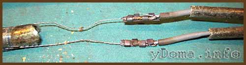
The ends of the nichrome spiral are connected to copper conductors electrical cord with a fork at the end. To ensure the reliability of this connection, the ends of the nichrome spiral are bent and folded in half, which reduces heating at the junction with copper wire. In addition, the connection is crimped with a metal plate; it is best to make the crimp from aluminum plate, which has high thermal conductivity and will more effectively remove heat from the joint. For electrical insulation, heat-resistant tubes are placed at the connection point. insulating material, fiberglass or mica.
The copper rod and nichrome spiral are closed with a metal case consisting of two halves or a solid tube, as in the photo. The body of the soldering iron is fixed on the tube with cap rings. To protect a person’s hand from burns, a handle made of a material that does not transmit heat well, wood or heat-resistant plastic, is attached to the tube.

When inserting the soldering iron plug into the outlet electricity goes to a nichrome heating element, which heats up and transfers heat to the copper rod. The soldering iron is ready for soldering.
Low-power transistors, diodes, resistors, capacitors, microcircuits and thin wires are soldered with a 12 W soldering iron. Soldering irons 40 and 60 W are used for soldering powerful and large-sized radio components, thick wires and small parts. To solder large parts, for example, heat exchangers of a geyser, you will need a soldering iron with a power of one hundred or more watts.
As you can see in the drawing electrical diagram The soldering iron is very simple, and consists of only three elements: a plug, a flexible electrical wire and a nichrome spiral.

As can be seen from the diagram, the soldering iron does not have the ability to adjust the heating temperature of the tip. And even if the power of the soldering iron is chosen correctly, it is still not a fact that the temperature of the tip will be required for soldering, since the length of the tip decreases over time due to its constant refilling; solders also have different temperatures melting. Therefore, to maintain optimal temperature soldering iron tips have to be connected through thyristor power regulators with manual adjustment and automatic maintenance of the set temperature of the soldering iron tip.
Calculation and repair of the heating winding of a soldering iron
During repairs or self-production an electric soldering iron or any other heating device has to be wound heating winding from nichrome wire. The initial data for calculating and selecting wire is the winding resistance of a soldering iron or heating device, which is determined based on its power and supply voltage. You can calculate what the winding resistance of a soldering iron or heating device should be using the table.
Calculation of a wire heater for an electric furnace.
This article reveals the biggest secrets in the design of electric furnaces - the secrets of heater calculations.
How are the volume, power and heating rate of a furnace related?
As stated elsewhere, there are no ordinary ovens. Likewise, there are no kilns for firing earthenware or toys, red clay or beads. There is simply a stove (and here we are talking exclusively about electric stoves) with a certain amount of usable space, made of some refractories. In this kiln you can place one large or small vase for firing, or you can put a whole stack of slabs on which thick fireclay tiles will lie. It is necessary to fire a vase or tiles, maybe at 1000 o C, and maybe at 1300 o C. For many production or household reasons, firing should take place in 5-6 hours or 10-12.
No one knows what you need from a stove better than you. Therefore, before you begin the calculation, you need to clarify all these issues for yourself. If you already have a stove, but you need to install heaters in it or replace old ones with new ones, there is no need for construction. If a furnace is being built from scratch, you need to start by finding out the dimensions of the chamber, that is, length, depth, width.
Let's assume you already know these values. Let's assume that you need a camera with a height of 490 mm, a width and a depth of 350 mm. Further in the text we will call an oven with such a chamber a 60-liter oven. At the same time, we will design a second furnace, larger, with height H=800 mm, width D=500 mm and depth L=500 mm. We will call this oven a 200-liter oven.
Oven volume in liters = H x D x L,
where H, D, L are expressed in decimeters.
If you correctly converted millimeters to decimeters, the volume of the first oven should be 60 liters, the volume of the second should really be 200! Don’t think that the author is being sarcastic: the most common errors in calculations are errors in dimensions!
Let's move on to the next question - what are the walls of the furnace made of? Modern furnaces are almost all made of lightweight refractories with low thermal conductivity and low heat capacity. Very old stoves are made of heavy fireclay. Such furnaces are easily recognized by their massive lining, the thickness of which is almost equal to the width of the chamber. If this is your case, you are out of luck: during firing, 99% of the energy will be spent on heating the walls, not the products. We assume that the walls are made of modern materials(MCRL-08, ShVP-350). Then only 50-80% of the energy will be spent on heating the walls.
The loading mass remains very uncertain. Although it is, as a rule, less than the mass of the refractories of the walls (plus the hearth and roof) of the furnace, this mass, of course, will contribute to the heating rate.
Now about the power. Power is how much heat the heater produces in 1 second. The unit of power is the watt (abbreviated W). A bright incandescent light bulb is 100 W, Electric kettle- 1000 W, or 1 kilowatt (abbreviated 1 kW). If you turn on a 1 kW heater, it will release heat every second, which, according to the law of conservation of energy, will go to heat the walls, products, and fly away with the air through the cracks. Theoretically, if there are no losses through cracks and walls, 1 kW is able to heat anything to an infinite temperature in an infinite time. In practice, real (approximate average) heat loss is known for furnaces, so there is the following rule-recommendation:
For a normal heating rate of a 10-50 liter oven, power is needed
100 W per liter of volume.
For a normal oven heating rate of 100-500 liters, power is needed
50-70 W per liter of volume.
The value of the specific power must be determined not only taking into account the volume of the furnace, but also taking into account the massiveness of the lining and loading. The greater the load mass, the higher value you need to choose. Otherwise, the oven will heat up, but longer time. Let’s choose a specific power of 100 W/l for our 60-liter tank, and 60 W/l for our 200-liter tank. Accordingly, we find that the power of the 60-liter heaters should be 60 x 100 = 6000 W = 6 kW, and the 200-liter heater should be 200 x 60 = 12000 W = 12 kW. Look how interesting it is: the volume has increased by more than 3 times, but the power has only increased by 2. Why? (Question for independent work).
It happens that there is no socket for 6 kW in the apartment, but there is only one for 4. But you need a 60-liter one! Well, you can calculate the heater at 4 kilowatts, but accept that the heating stage during firing will last 10-12 hours. It happens that, on the contrary, it is necessary to heat up a very massive load in 5-6 hours. Then you will have to invest 8 kW into a 60-liter stove and not pay attention to the red-hot wiring... For further discussion, we will limit ourselves to classic powers - 6 and 12 kW, respectively.
Power, amperes, volts, phases.
Knowing the power, we know the heat requirement for heating. According to the inexorable law of conservation of energy, we must take the same power from the electrical network. We remind you of the formula:
Heater Power (W) = Heater Voltage (V) x Current (A)
or P = U x I
There are two pitfalls in this formula. First: the voltage must be taken at the ends of the heater, and not generally at the outlet. Voltage is measured in volts (abbreviated as V). Second: we mean the current that flows specifically through this heater, and not through the machine in general. Current is measured in amperes (abbreviated as A).
We are always given the voltage in the network. If the substation is operating normally and it is not rush hour, the voltage in a regular household outlet will be 220 V. The voltage in an industrial three-phase network between any phase and neutral wire is also 220V, and the voltage between any two phases- 380 V. Thus, in the case of a household, single-phase network, we have no choice in voltage - only 220 V. In the case of a three-phase network, there is a choice, but small - either 220 or 380 V. But what about amperes? They will be obtained automatically from the voltage and resistance of the heater according to the great law of the Great Ohm:
Ohm's law for a section of an electrical circuit:
Current (A) = Section Voltage (V) / Section Resistance (Ohm)
or I = U/R
In order to get 6 kW from a single-phase network, you need current I=P/U= 6000/220 = 27.3 amperes. This is a large, but real current of a good household network. For example, such a current flows in an electric stove with all the burners turned on at full power and the oven too. To get 12 kW in a single-phase network for a 200-liter tank, you will need twice the current - 12000/220 = 54.5 amperes! This is not acceptable for any household network. It is better to use three phases, i.e. distribute power over three lines. Each phase will flow 12000/3/220 = 18.2 amperes.
Let's pay attention to the last calculation. On this moment we DO NOT KNOW what kind of heaters will be in the oven, we DO NOT KNOW what voltage (220 or 380 V) will be supplied to the heaters. But we KNOW for sure that 12 kW needs to be taken from a three-phase network and the load distributed evenly, i.e. 4 kW in each phase of our network, i.e. 18.2A will flow through each phase wire of the input (general) furnace circuit breaker, and it is not at all necessary that such a current will flow through the heater. By the way, 18.2 A will also pass through the electricity meter. (And by the way: there will be no current along the neutral wire due to the features of three-phase power supply. These features are ignored here, since we are only interested in the thermal work of current). If you have questions at this point in the presentation, read everything again. And think: if 12 kilowatts are released in the volume of the furnace, then, according to the law of conservation of energy, the same 12 kilowatts pass through three phases, each with 4 kW...
Let's return to the single-phase 60-liter stove. It is easy to find that the resistance of the furnace heater should be R=U/I= 220 V / 27.3 A = 8.06 Ohm. Therefore, in the very general view The electrical circuit of the furnace will look like this:
A heater with a resistance of 8.06 Ohms should carry a current of 27.3 A
For a three-phase oven, three identical heating circuits will be required: the figure shows the most general electrical circuit of a 200-liter oven.
The power of a 200-liter stove must be evenly distributed over 3 circuits - A, B and C.
But each heater can be switched on either between phase and zero, or between two phases. In the first case, there will be 220 volts at the ends of each heating circuit, and its resistance will be R=U/I= 220 V / 18.2 A = 12.08 Ohm. In the second case, there will be 380 volts at the ends of each heating circuit. To obtain a power of 4 kW, the current must be I=P/U= 4000/380 = 10.5 amperes, i.e. there must be resistance R=U/I= 380 V / 10.5 A = 36.19 Ohm. These connection options are called "star" and "delta". As can be seen from the values of the required resistance, it will not be possible to simply change the power supply circuit from a star (12.08 Ohm heaters) to a triangle (36.19 Ohm heaters) - in each case you need your own heaters.
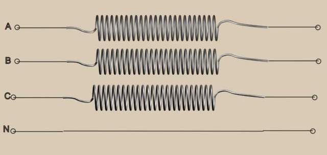
In a star circuit, each heating circuit
connected between phase and zero at a voltage of 220 Volts. Each heater with a resistance of 12.08 Ohms carries a current of 18.2 A. No current flows through wire N.

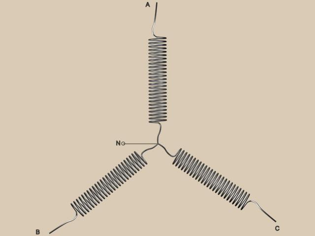
In a delta circuit, each heating circuit
connected between two phases at a voltage of 380 Volts. Each heater with a resistance of 36.19 Ohms carries a current of 10.5 A. The wire connecting point A1 to the power supply (point A) carries a current of 18.2 A, so 380 x 10.5 = 220 x 18.2 = 4 kilowatt! Similarly with lines B1 - B and C1 - C.
Homework. There was a star in the 200-liter bottle. The resistance of each circuit is 12.08 Ohms. What will be the power of the furnace if these heaters are turned on in a triangle?
Maximum loads of wire heaters (Х23У5Т).
Complete victory! We know the heater resistance! All that remains is to unwind a piece of wire of the required length. Let's not get tired of calculations with resistivity - everything has long been calculated with sufficient accuracy for practical needs.
| Diameter, mm | Meters per 1 kg | Resistance 1 meter, Ohm |
| 1,5 | 72 | 0.815 |
| 2,0 | 40 | 0.459 |
| 2,5 | 25 | 0.294 |
| 3,0 | 18 | 0.204 |
| 3,5 | 13 | 0.150 |
| 4,0 | 10 | 0.115 |
For a 60-liter furnace you need 8.06 Ohms, let’s choose one and a half racks and find that the required resistance will be provided by only 10 meters of wire, which will weigh only 140 grams! Amazing result! Let's check again: 10 meters of wire with a diameter of 1.5 mm has a resistance of 10 x 0.815 = 8.15 Ohms. The current at 220 volts will be 220 / 8.15 = 27 amperes. The power will be 220 x 27 = 5940 Watts = 5.9 kW. We wanted 6 kW. We haven’t made a mistake anywhere, the only alarming thing is that such stoves don’t exist...
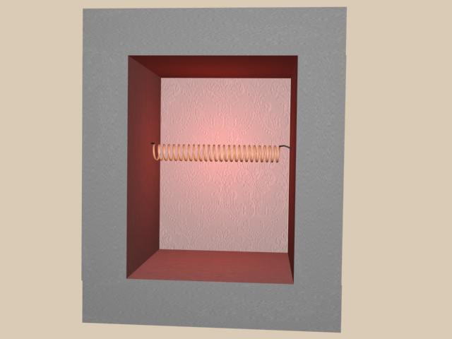
A single hot heater in a 60-liter oven.
The heater is very small, or something. This is the feeling one gets when looking at the above picture. But we are engaged in calculations, not philosophy, so let’s move from sensations to numbers. The numbers say the following: 10 linear meters of wire with a diameter of 1.5 mm have an area S = L x d x pi = 1000 x 0.15 x 3.14 = 471 sq. cm. From this area (where else?) 5.9 kW is radiated into the volume of the furnace, i.e. per 1 sq. cm of area the emitted power is 12.5 watts. Omitting the details, we point out that the heater needs to heat up to a huge temperature before the temperature in the furnace increases significantly.
The overheating of the heater is determined by the value of the so-called surface load p, which we calculated above. In practice, there are limit values for each type of heater p, depending on the heater material, diameter and temperature. With a good approximation, for wire made of the domestic alloy X23Yu5T of any diameter (1.5-4 mm), you can use a value of 1.4-1.6 W/cm 2 for a temperature of 1200-1250 o C.
Physically, overheating can be associated with the difference in temperature on the surface of the wire and inside it. Heat is released throughout the entire volume, so the higher the surface load, the more these temperatures will differ. When the surface temperature is close to the operating limit temperature, the core temperature of the wire may approach the melting point.
If the furnace is designed for low temperatures, the surface load can be chosen larger, for example, 2 - 2.5 W/cm 2 for 1000 o C. Here we can make a sad remark: real kanthal (this is an original alloy, an analogue of which is the Russian fechral X23Yu5T) allows p up to 2.5 at 1250 o C. This type of kanthal is made by the Swedish company Kanthal.
Let's return to our 60-liter tube and select a thicker wire from the table - two. It is clear that twos will have to take 8.06 Ohm / 0.459 Ohm/m = 17.6 meters, and they will already weigh 440 grams. We calculate the surface load: p= 6000 W / (1760 x 0.2 x 3.14) cm 2 = 5.43 W/cm 2. A lot of. For a wire with a diameter of 2.5 mm, the result is 27.5 meters and p= 2.78. For three - 39 meters, 2.2 kilograms and p= 1.66. Finally.
Now we will have to wind 39 meters of the three-piece (if it bursts, start winding again). But you can use TWO heaters connected in parallel. Naturally, the resistance of each should no longer be 8.06 Ohms, but twice as much. Therefore, for a double, you get two heaters of 17.6 x 2 = 35.2 m, each with 3 kW of power, and the surface load will be 3000 W / (3520 x 0.2 x 3.14) cm 2 = 1, 36 W/cm2. And weight - 1.7 kg. We saved half a kilo. We got a lot of turns in total, which can be evenly distributed over all the walls of the furnace.

Well distributed heaters in a 60 liter oven.
| Diameter, mm | Current limit for p=2 W/cm 2 at 1000 o C | Current limit for p=1.6 W/cm 2 at 1200 o C |
| 1,5 | 10,8 | 9,6 |
| 2,0 | 16,5 | 14,8 |
| 2,5 | 23,4 | 20,7 |
| 3,0 | 30,8 | 27,3 |
| 3,5 | 38,5 | 34,3 |
| 4,0 | 46,8 | 41,9 |
An example of calculating a 200 liter stove.
Now that the basic principles are known, we will show how they are used in calculating a real 200 liter stove. All stages of the calculation, naturally, can be formalized and written into a simple program that will do almost everything itself.
Let's draw our oven "in development". We seem to be looking at it from above, in the center - underneath, on the sides of the wall. We will calculate the areas of all the walls so that we can then correctly organize the heat supply in proportion to the area.
"Unwrapping" of a 200-liter stove.
We already know that when connected by a star, a current of 18.2A should flow in each phase. From the above table on limiting currents it follows that for a wire with a diameter of 2.5 mm you can use one heating element (maximum current 20.7 A), and for a 2.0 mm wire you need to use two elements connected in parallel (since the maximum current is only 14.8A), in total there will be 3 x 2 = 6 in the oven.
Using Ohm's law, we calculate the required resistance of the heaters. For wire with a diameter of 2.5 mm R= 220 / 18.2 = 12.09 Ohms, or 12.09 / 0.294 = 41.1 meters. You will need 3 of these heaters, approximately 480 turns each, if wound on a 25 mm mandrel. Total weight wire will be (41.1 x 3) / 25 = 4.9 kg.
For a 2.0 mm wire, there are two parallel elements in each phase, so the resistance of each should be twice as large - 24.18 Ohms. The length of each will be 24.18 / 0.459 = 52.7 meters. Each element will have 610 turns at the same winding. Total weight of all 6 heating elements(52.7 x 6) / 40 = 7.9 kg.
Nothing prevents us from dividing any spiral into several pieces, which are then connected in series. For what? Firstly, for ease of installation. Secondly, if a quarter of the heater fails, only that quarter will need to be replaced. In the same way, no one bothers you to put a solid spiral into the oven. Then the door will need a separate spiral, and in the case of a diameter of 2.5 mm, we have only three of them...
We installed one phase of 2.5 mm wire. The heater was divided into 8 independent short spirals, all of them connected in series.
When we put all three phases in a similar way (see figure below), the following becomes clear. We forgot about the under! And it occupies 13.5% of the area. In addition, the spirals are in dangerous electrical proximity to each other. The proximity of the spirals on the left wall, where the voltage between them is 220 Volts (phase - zero - phase - zero...), is especially dangerous. If for some reason the adjacent spirals of the left wall touch each other, a large short circuit cannot be avoided. We suggest that you independently optimize the location and connection of the spirals.

All phases have been installed.
In case we decide to use a two, the diagram is shown below. Each element, 52.7 meters long, is divided into 4 successive spirals of 610 / 4 = 152 turns (winding on a 25 mm mandrel).

Option for the location of heaters in the case of 2.0 mm wire.
Features of winding, installation, operation.
The wire is convenient because it can be wound into a spiral, and the spiral can then be stretched as convenient. It is believed that the coiling diameter should be greater than 6-8 wire diameters. Optimal step between the turns there is 2-2.5 wire diameters. But you have to wind it turn by turn: stretching the spiral is very easy, compressing it is much more difficult.
Thick wire may break during winding. It’s especially frustrating if there are only 5 turns left to wind out of 200. It is ideal to wind on a lathe at a very slow rotation speed of the mandrel. Alloy Kh23Yu5T is produced tempered and untempered. The latter breaks especially often, so if you have a choice, be sure to purchase wire tempered for winding.
How many turns are needed? Despite the simplicity of the question, the answer is not obvious. Firstly, the diameter of the mandrel and, consequently, the diameter of one turn is not known exactly. Secondly, it is known for sure that the diameter of the wire varies slightly along its length, so the resistance of the spiral will also vary. Thirdly, the resistivity of a specific alloy may differ from the reference one. In practice, they wind the spiral 5-10 turns more than calculated, then measure its resistance - with a VERY ACCURATE device that you can trust, and not with a soap dish. In particular, you need to make sure that with short-circuited probes the device shows zero, or a number on the order of 0.02 Ohm, which will need to be subtracted from the measured value. When measuring resistance, the spiral is slightly stretched to eliminate the influence of interturn short circuits. The extra turns are bitten off.
It is best to place the spiral in a furnace on a mullite-silica tube (MSR). For a coiling diameter of 25 mm, a tube with an outer diameter of 20 mm is suitable, for a coiling diameter of 35 mm - 30 - 32 mm.
It’s good if the stove is heated evenly on five sides (four walls + underneath). Significant power must be concentrated on the hearth, for example, 20 -25% of the total design power of the furnace. This compensates for the suction of cold air from outside.
Unfortunately, absolute heating uniformity still cannot be achieved. You can get closer to it using ventilation systems with BOTTOM air intake from the furnace.
During the first heating or even the first two or three heatings, scale forms on the surface of the wire. We must remember to remove it both from the heaters (with a brush) and from the surface of slabs, bricks, etc. Scale is especially dangerous if the spiral is simply lying on the bricks: iron oxides with aluminosilicates when high temperature(the heater is one millimeter away!) form fusible compounds, due to which the heater can burn out.