Scheme of gravity heating of a two-story house. Do-it-yourself heating of a two-story private house - diagrams
Two-story houses have gained great popularity throughout our country. They are valued not only for their comfort, but also for rational use land area, savings in building materials and relative simplicity construction. At the same time, competently organizing the heating of a two-story home is not an easy task. There are subtleties and secrets here, without knowledge of which the house will be heated unevenly or ineffectively. Let's discuss the main heating systems that you can consider for a two-story home.
A feature of the heating system with natural circulation of a two-story house is the absence of a pump that creates pressure in the pipes. The movement of water is ensured by the laws of hydraulics and thermodynamics, for which the pipes are installed at a certain angle to each other at a given height. Although this system has slightly lower thermal efficiency, it is completely autonomous, that is, it does not depend on power supply and does not consume additional energy.
Heating with natural circulation of a two-story house can be performed using either a single-pipe or a two-pipe scheme. The advantages and disadvantages of these types are discussed in detail below. Here are a few features to keep in mind when organizing any type of natural circulation:
- large diameter pipes will be required, otherwise the movement of water will be difficult;
- It is unacceptable to use closed expansion tanks - this entails the creation of excess pressure and the system will no longer work by gravity;
- the highest point of the pipeline is chosen as the location of the expansion tank, while the boiler is located below, most often slightly below the return line.
When installing a system with natural circulation in two-story house Significant waste of materials and a decrease in heat transfer are inevitable. Such difficulties are justified only in one case - when the risk of power outages during the cold season is too great.
Single-pipe heating systems

A two-story house is understood as a complex of radiators that use the same line to receive hot coolant and discharge cooled coolant. This allows significant savings on materials, but entails a number of disadvantages:
- increased boiler power is required;
- the temperature of the water in the lines consistently decreases from radiator to radiator;
- each subsequent radiator must have more sections than the previous one (which is a consequence of the previous point).
So the implementation single-pipe schemes It makes sense only in regions with a relatively mild climate for heating small houses.
Heating "Leningradka"
As you might guess, this heating scheme was developed in the Soviet Union and was widely implemented in small buildings in the northern capital. The basis of the “Leningradka” is one common highway running along the perimeter of the premises below the level of installation of radiators. The pipes cut into it from above, and to redirect the coolant flow, a pipe is narrowed under each radiator or a control valve is installed.
Both natural and forced circulation are possible. In the first case, it is recommended to install no more than four radiators, in the second - no more than six. Connecting seven to eight radiators is possible only after precise engineering calculations; with a larger number of heat consumers, the system is considered ineffective.
Alternative types of single-pipe heating
A further evolution of the “Leningradka” can be considered systems with breaks in the main line and sub-radiator constrictions, which act as “bottlenecks”, redirecting the flow of liquid. This allows you to simplify the main line, getting rid of narrowings and valves, and also to locate radiators away from the area where the main pipes are laid. With sufficient power of the injection pump in forced circulation cycles, a slight increase in the heated areas is possible.
Two-pipe heating

It has found application in large two-story houses, as it has significantly lower heat loss from radiator to radiator. The structure of the system includes two main lines: hot and cold. In the first, the heated liquid is supplied to heat consumers, in the second, the cooled coolant is discharged. In this case, the highways do not have any direct connection with each other.
On a separate primary branch of the hot main, it is significantly higher than the pipelines. Closed models are usually selected. Valves can be installed in front of radiators, allowing you to selectively turn off individual rooms from heating, but closing too many valves can lead to excess pressure and leaks, especially in systems with forced circulation and with incorrectly performed thermal calculations.
Dead-end circuit and Tichelman loop
Initially, all two-pipe heating systems worked according to a direct dead-end circuit. This meant that the radiator, which was the first to receive hot coolant, was the first to release cooled coolant, which entailed a consistent loss of pressure in the radiators and a decrease in their efficiency. Although not as significant as with a single-pipe arrangement. The dead-end circuit is still used for heating small buildings, as it requires significantly less material consumption during installation and is not so demanding on pump power.
A solution to the problem of pressure drop was proposed by engineer Albert Tichelman. He developed a reversible coolant return system, or, more simply, a return loop. Thus, the radiator that first received the coolant discharged it last, and the last installed radiator drained the cooled liquid earlier than the others. At the same time, of course, the length of the return line doubled. The dead-end circuit is well suited for heating a two-story house.
Beam scheme

Another branch of the evolution of a dead-end heating system was the so-called radial scheme. It assumes the presence of an additional unit - a distribution manifold. It is necessary for dividing the primary and return lines to each radiator separately, which ensures the circulation of liquid with equal temperature and equal pressure in all elements of the system.
Further complexity of the heating system compared to dead-end and loop-type schemes led to even greater consumption of pipes when laying mains. However, it pays off in high efficiency. The requirements for the expansion tank and injection pump are the same as in the “Tichelman loop”.
Heating with heated floors
The main “trick” of a heated floor is the installation of one large, but low-power “radiator” in underground space, instead of using a system of standard mounted radiators. This ensures more uniform heat distribution, increases indoor comfort and, with proper implementation of the system, reduces energy costs. However, heated floors are not without their drawbacks. These include:
- long time to warm up a completely cooled room;
- the possibility of condensation due to almost complete isolation from external factors;
- complexity of calculation and installation of the system.

Recent studies have noted that, all other factors being equal, a room with a heated floor can be heated to a temperature 2ºC lower than a room with classical heating, and this will not affect human comfort in any way. This fact alone allows you to save up to 10-15% energy.
Today, quite often, heated floors are used for heating a two-story house. The system can act as the main one, but for this it is important to make all the thermal calculations.
Heating with gas boiler

Gas boilers are the main source of energy in most modern heating systems. They guarantee high performance at relatively low energy costs, are highly reliable and safe, of course, subject to all installation standards and regulations.
However, in last years There is a trend of constant growth in prices for natural gas, which will soon equate the specific costs of its purchase with the costs of maintaining an electric heating system. And two-story houses are most often built with large areas. As long as gas availability remains, we recommend heating your two-story house with a gas boiler.
Which heating scheme should I choose?
When choosing a specific type of heating system, you should be guided, first of all, by the characteristics of the building, pay attention to the availability of electricity and financial capabilities. If you have engineering documents, look at them, as a rule, all the necessary numbers are indicated. Otherwise, you will have to carry out all the measurements yourself. Minimum Required- floor area, room volume, thickness and material load-bearing walls and partitions.
After this it is worth analyzing climatic features region, the cost and availability of various types of energy. Based on these data, a primary selection of options for organizing heating is made, after which the planned costs for their acquisition and installation, as well as future maintenance, are calculated. Exactly economic indicators, both short-term and strategic, are decisive when choosing specific type heating.
If there are difficulties with finances, the availability of light is unstable, and the only energy source is coal, then perhaps you should look towards simple one-pipe heating systems. If there is gas, stable supply light and finances allow, then you can look towards two-pipe and beam systems heating a two-story house.
4 351
It is extremely necessary for the construction of a house to have an accurate solution for the heating system, since the comfort of the residents is associated with it when it is cold. The heating circuit must make heating the building a problem. This is due to both accurate selection and correct installation work.
The following must be available: a heating boiler, a manifold, a pipeline and a heating unit. Water in such a system circulates using. Gas, kerosene, firewood, and coal are used to heat the boiler. This is also possible using electricity or other alternatives.

Forced circulation heating circuit
They are connected using high temperature soldering using solder that contains silver. If desired, you can hide the pipes in the walls, which will be quite beautiful and convenient. The disadvantage of such pipes is their considerable cost, but this is the only drawback. Such pipes are very reliable and recommended. If installed correctly, they can last for generations of residents. There will be no need to replace or repair pipes. This type of pipe is of high quality and quite reliable.
They have their own advantages - they are convenient to install, which even an installer without specialized education can do, which will provide significant financial savings. There is no deposit of sediment inside polymer pipes, which means that these pipes will not clog very quickly and will be resistant to corrosive processes. Installation of such pipes occurs using threaded or press-type connections without welding. The disadvantage is the rather high rate of thermal expansion. This may cause a leak.
When, you need to think about the type of pipes that are most suitable for a given building, taking into account alternative and emergency heating. It goes without saying that many factors have a material basis. But the best solution will not save on the heating system. This factor will influence living conditions in winter and whether residents will be able to enjoy living in comfort and warmth.
Professional advice is to choose a copper pipeline. Such a pipeline will be able to serve its owners long and reliably for a couple of generations. The price of such a pipeline will be higher, but the reliability will also be higher.
In buildings with two floors, the following heating distribution schemes are most often used: collector, two-pipe and single-pipe.
It is quite difficult to make adjustments using the circuit. This is due to the fact that there is no possibility of shutting off one of the radiators, provided that all other heating devices are in operation. For this reason, as hot water is transferred from one radiator to another, it loses more and more temperature.

Single-pipe wiring diagram
Wiring diagram would be better suited for houses with two floors.

Two-pipe wiring diagram
Due to the fact that each heating device has two pipes. Through one it's hot water. Already cooled water flows through the second. Another difference between this system and a single-pipe system is a different procedure for connecting heating devices. Professionals recommend installing a control tank in front of all radiators.
For normal circulation in the building, the distance between the center of the boiler and the highest point of the supply line is sufficient. Under such conditions, it is possible to install the expansion tank on the floor above, and not in the attic. In this case, the supply pipe is laid from below the window sill or under the ceiling.
If a two-pipe type scheme with natural circulation is used, this requires additional heating of the entire heating system.
For this reason, additional installation with a circulation pump is recommended. This will provide significant time savings when turning on a similar system, such as a heating model for a house with two floors. Under such conditions, heat will be distributed more evenly in the building.
In addition to installing batteries, in a house with two floors and when using a boiler with a built-in circulation pump, it is possible to install a “warm floor” system. There is also the possibility of connecting a towel dryer on two floors at once.

Heating scheme with heated floors
When doing installation work, it would be best to use a collector. This system is the most convenient and it is possible to adjust the temperature in all rooms. For all heating devices, two pipes are laid: return and direct. Collectors are installed on all floors. It is important that they are in the closet that is intended for this purpose. All shut-off valves are located in the same cabinet.
Provides the ability to implement a heating scheme with a hidden type of pipes. Installation is quite simple. For this reason, it can be produced even by an employee without professional skills.

Water-type heating can be carried out on one floor, or even on all floors at the same time. It is recommended that the boiler be installed exclusively on the ground floor. It is already possible to install on the second floor expansion tank.
It is advisable that the pipes through which hot water flows are laid from below the window sill or under the ceiling. These will be the most vulnerable points to cold air. It will be important to install a separate tap on all batteries for adjustment.
When choosing a heating model, you will also need to accept the right decision. This is related to the extent to which it will be convenient for residents in frosty weather, the service life of the entire system and the frequency of the need for repair or replacement of pipes and other factors. If the choice turns out to be wrong, with plans for quick financial savings, it may be that there will be a constant need for repairs, replacements, and hiring builders. This, in turn, will bring cash expenses. For this reason, there can be no talk of financial savings.
The best solution would be to install at the very beginning of the pipes High Quality, radiators and everything else. It is possible that at the moment all this will be more expensive, but at the same time there will be long term work and as a result will be more economical in the future. A properly built heating system for a two-story home using sustainable, good quality materials can last for generations.
Your contacts in this article from 500 rubles per month. Other mutually beneficial options for cooperation are possible. Write to us at [email protected]
System autonomous heating private country house– in itself is a very difficult project in terms of planning and practical implementation. It is necessary to take into account a lot of nuances, carry out the necessary thermal calculations, correctly select all the equipment required for the system by type and technical characteristics, decide on the diagrams for its installation and laying the necessary communications, competently carry out installation and carry out commissioning work. All this is done to ensure that the creation in residential premises the most optimal microclimate was fully combined with the ease of operation of the heating system, the reliability of its operation and, without fail, with the highest possible efficiency.
Well, if a heating scheme for a 2-story private house is being developed, then the task becomes even more difficult. Not only is the number of premises and the length of thermal routes increasing. It is important to achieve the necessary uniform distribution of heat throughout all rooms, regardless of what floor they are located on and what area they have.
This publication will examine the main elements of the heating system of a private home and provide several schemes that have already been tested in operation. Of course, it is necessary to mention the advantages and disadvantages of each option.
What heating systems are there?
First of all, it is necessary to consider and compare the two basic circuits– open and closed heating systems. What is their main difference?
A coolant circulates through the pipes - a liquid with a high heat capacity, transferring thermal energy from the place of heating - the heating boiler, to the heat exchange points - radiators, convectors, underfloor heating circuits, etc. Like any physical body, a liquid has the property of expanding when the temperature increases. But, unlike, for example, gases, it is an incompressible substance, that is, it is tedious to provide a place for the excess volume that appears so that the pressure in the pipes, according to the laws of thermodynamics, does not increase to critical values.
For this purpose, an expansion tank is provided in any heating system with liquid coolant. Its design and installation location determine the division of heating systems into closed and open.
- Device principle open system heating is shown in the diagram:

1 – heating boiler.
2 – supply pipe (riser).
3 – expansion tank open type.
4 – heating radiators.
5 – return pipe
6 – pump unit.
The expansion tank is an open container of factory or handicraft production. It has an inlet pipe that is connected to the supply riser. It can be supplemented with pipes to prevent overflow when filling the system, to replenish the lack of coolant (water).

The main condition is that the expansion tank itself must be installed at the highest point of the system. This is necessary, firstly, so that excess coolant does not simply overflow outward according to the rule of communicating vessels, and secondly, it serves as an effective air vent– all gas bubbles formed during the operation of the system rise to the top and freely escape into the atmosphere.
No. 6 in the diagram shows the pumping unit. Although very often open-type systems are organized according to the principle of natural coolant circulation, installing a pump never hurts. Moreover, if you tie it correctly, with a bypass loop and shut-off valves, this will make it possible, as necessary, to switch from natural circulation to forced circulation and back.

By the way, installing an open expansion tank at the top point of the supply pipe is not at all a mandatory rule. There are possible options here, the choice of which is made based on the specific features of a particular heating system:

a – the tank is located at the highest point of the main supply pipe leaving the boiler. One might say - a classic version
b – the expansion tank is connected by a pipe to the “return”. Sometimes you have to resort to this arrangement, although it has significant drawback– the tank does not fully perform its functions air vent, and in order to avoid gas locks, such a device will have to be installed with special taps on risers or directly on heating radiators.
c – the tank is installed on the far supply riser.
d – rare location of the tank with pump unit immediately after it on the supply pipe.
- Below is a diagram of a closed type heating system:

The numbering of common elements is preserved by analogy with the previous scheme. What are the main differences?
The system has a sealed expansion tank (7), which has special design. It is divided by a special elastic membrane into two halves - a water and an air chamber.

This tank works very simply. With thermal expansion of the coolant, its excess enters the closed tank, increasing in volume water chamber due to stretching or deformation of the membrane. Accordingly, pressure increases in the opposite air chamber. As the temperature drops, air pressure pushes the coolant liquid back into the system pipes.
Prices for expansion tanks
expansion tank
Such an expansion tank can be installed almost anywhere in the heating system. Very often it is located in close proximity to the boiler on the return pipe.
Since the system is completely sealed, you should protect yourself from a critical increase in pressure in it in emergency situations. This necessitates another element - a safety valve, set to a certain response threshold. Typically this device is included in the so-called "security group"(on the diagram - No. 8). Its standard equipment includes:

"Security group" assembled
1 – control and measuring a device for visually monitoring the state of the system: a pressure gauge or a combined device - a pressure gauge-thermometer.
2 – automatic air vent.
3 – safety valve with preset upper pressure threshold or with the ability to independently regulate this parameter.
The security group is usually placed in such a way that the state of the system can be easily monitored. Often it is installed right next to the boiler. In this case, the upper sections of the heating system will require additional air vents on risers or on radiators.
Systems with natural and forced circulation
The principles of natural and forced circulation have already been mentioned in passing, but it is worth taking a closer look at them.
- The natural movement of coolant along heating circuits is explained by the laws of physics - the difference in density of hot and cooled liquid. To understand the principle, let's look at the diagram:

1 – point of primary heat exchange, boiler, where the cooled coolant receives heat from external energy sources.
2 – pipe for supplying heated coolant.
3 – secondary heat exchange point – heating radiator installed in the room. It should be located above the boiler by an amount h.
4 – return pipe running from the radiators to the boiler.
The density of a hot liquid (Pgor) is always significantly less than that of a cooled liquid (Rohl). The heated coolant, therefore, cannot have any significant effect on a denser substance. Therefore, you can conditionally remove the top “red” part of the circuit, and consider the processes in the return pipe.
The result is “classical” communicating vessels, one of which is located higher than the other. Such a hydraulic system always strives for balance - to ensure equal levels in both vessels. Due to the excess of one over the other, a constant flow of liquid towards the boiler occurs in the return pipe. Such a naturally created pressure with proper planning of the wiring is sufficient for the general circulation of the coolant through a closed heating circuit.
You might be interested in information about what it is
The greater the excess of radiators over the boiler (h), the more active the natural movement of liquid is, but it should not exceed 3 meters. Very often, in order to achieve an optimal location, the boiler is installed in the basement or basement. If this cannot be done, then they try to slightly lower the floor level in the boiler room.
To facilitate and stabilize natural circulation, it is also assisted by gravity - all circuit pipes are placed with a slope (from 5 to 10 mm per linear meter).
- The forced circulation system requires the mandatory installation of a special electric pump of the required capacity.
As already mentioned, the system can be combined - a properly connected pump will allow switching from one circulation principle to another. This is especially important in cases where the electricity supply in the area where you live is not stable.
The optimal location for the pump is considered to be the return pipe in front of the boiler entrance. This is certainly not a dogma, but in this area it will be less affected by high coolant temperatures and will last longer. Currently, they are increasingly being purchased that structurally already contain a circulation pump with the required parameters.
Prices for different types of heating boilers
heating boiler
Advantages and disadvantages of various systems
First of all, it should be noted that there is no clear division of systems according to the two mentioned parameters at once. Thus, an open system can operate on the principles of both natural and forced circulation, depending on its design features. The same can be said to a certain extent about a closed hermetic system, although already- With certain assumptions.
But if we look at the projects presented on the Internet, we will notice that an open system more often involves natural circulation or a combined one, with the possibility of switching. Closed heating circuits most often provide for the installation of forced circulation - this way they work more correctly and are easier to adjust.
So, let's look at the main advantages and disadvantages of both systems.
In the beginning - oh merits open system with natural circulation.
- In an open type system, the expansion tank performs several functions at once.
— This scheme does not require the installation of a safety group, since the pressure can never reach critical values.
— Installation of the expansion tank at the highest point on the supply pipe ensures spontaneous release of accumulated gas bubbles. Most often, this is quite enough, and installing additional air vents not required.
- The system is extremely reliable in terms of operation, as it does not contain complex components. In fact, its “life” is determined only by the condition of the pipes and radiators.
- There is no complete dependence on the power supply, no electricity is consumed.
- The absence of electromechanical components means silent heating operation.
- Nothing prevents you from equipping the system with forced circulation.
- The system has interesting property self-regulation - the intensity of circulation of the coolant depends on the rate of its cooling in the radiators, that is, on the air temperature in the rooms. The higher the heating, the lower the flow rate. This often allows the system to be balanced without the use of complex adjustment devices.
Now - about her shortcomings:
- The rule for installing an expansion tank at the highest point often leads to the need for its location in the attic. If the attic is cold, then reliable thermal insulation of the tank will be required - to prevent serious heat losses and to avoid freezing in low winter temperatures.
- An open tank does not prevent the coolant from contacting the atmosphere. And this, in turn, entails two negative aspects:
— Firstly, the coolant evaporates, which means you need to monitor its level. In addition, this limits the owners in choosing a coolant - the evaporation of antifreeze entails certain material costs. Moreover, the concentration of chemical components may also change, and for some boilers (for example, electrolytic ones) this is unacceptable.
“Secondly, the liquid is constantly saturated with oxygen from the air. This leads to the activation of corrosion processes (steel and aluminum radiators). And the second negative is increased gas formation during the heating process.

Aluminum radiators for open heating systems are of little use
- Such a system causes certain difficulties during installation - it is necessary to maintain the required level of slope. In addition, pipes of different diameters will be required, including large ones, since for each section with natural circulation it is necessary to maintain the required cross-section. This circumstance also complicates installation and leads to significant material costs, especially when using metal pipes.
- The capabilities of such a system are very limited - if the distance from the boiler is too great, the hydraulic resistance of the pipes may be higher than the natural liquid pressure created, and circulation will become impossible. By the way, this completely excludes the possibility of using “warm floors” without special additional equipment.
- The system is very inert, especially during a “cold start”. A serious starting “impulse” is required, that is, starting at high power to ensure the start of fluid circulation. For the same reasons - there are certain difficulties in finely balancing the system across floors and rooms.
Now let's look at closed system with forced circulation.
Her dignity:
- Given that correct selection The circulation pump system is not limited either by the number of floors of the building or by its plan size.
- Forced circulation ensures faster and more uniform heating of radiators during startup. It is much easier to make fine adjustments.
- The coolant does not evaporate and is not saturated with oxygen. There are no restrictions on the type of liquid or the type of radiator.
- The tightness of the system prevents air from entering pipes and radiators. Gas formation in the liquid gradually disappears over time and is easily eliminated air vents.
- It is possible to use pipes of smaller diameter. When installing them, no slope is required.
- The expansion tank can be installed in any place convenient for the owners in a heated room - the likelihood of it freezing is completely eliminated.
- The temperature difference at the boiler outlet and in the “return” with stable heating operation is significantly less. This circumstance significantly increases the service life of the equipment.
- This system is the most flexible in terms of the use of heating devices. It is suitable for “classic” radiators, and for convectors and “heat curtains”, wall-mounted or hidden, and for “warm floor” circuits.
Disadvantages not much, but they are still there:
- For correct operation, it will be necessary to carry out a preliminary calculation of all components of the system - boiler, radiators, circulation pump, expansion tank, in order to achieve complete consistency in their functioning.
- It is impossible to do without installing a “security group”.
- Perhaps the most important drawback is the dependence on the stability of the electricity supply.

Most likely, this will require the purchase and installation of uninterruptible power supplies (if the design does not allow for the possibility of switching to natural circulation with a non-volatile boiler).
You may be interested in information about what they are
Prices for uninterruptible power supplies
uninterruptable power source
Wiring diagrams in a two-story house
How to route heating pipes throughout a two-story house? There are several schemes, from the simplest to the quite complex.
First of all, you need to decide whether the system will be one pipe or two pipe.
- An example of a one-pipe system is shown in the diagram:

One-pipe system is the most imperfect
The heating radiators seem to be “strung” onto one pipe, which is looped from the outlet to the entrance to the boiler and through which both the supply and removal of coolant are carried out. The obvious advantages of such a scheme are its simplicity and minimum consumption materials during installation. Unfortunately, this is where its advantages end.
It is quite obvious that the fluid temperature drops from radiator to radiator. Thus, in rooms located closer to the boiler room, the temperature of the batteries will be significantly higher than in rooms located further away. Of course, this can be compensated to some extent by a different number of heating sections, but this is seen only in small houses. Considering that the article is about a two-story building, then such a scheme is unlikely to be the optimal solution.
Some problems are solved by installing a single-pipe system - “Leningradka”, the diagram of which is shown in the figure below. The input and output of each battery in this case are connected to each other by a bypass jumper, and heat loss as it moves away from the boiler is no longer so significant.

The Leningradka scheme eliminates some of the problems
"Leningradka" lends itself to even greater modernization. So, you can install a control valve on the bypass. The same valves can be installed on one or even both radiator pipes (shown by arrows). It immediately opens ample opportunities in finer tuning of the heating system for each room separately. There is access to each radiator - if necessary, it can simply be turned off or removed for replacement, without at all interfering with the functionality of the entire circuit.

Improved "Leningradka" with shut-off and balancing valves
By the way, with its flexibility, simplicity, and low pipe consumption, “Leningradka” has gained enormous popularity - it can often be found in one-story houses (especially with a significantly large wall perimeter) and in high-rise buildings. It is quite suitable for a two-story mansion.
And yet it is not without its shortcomings. The possibility of connecting underfloor heating circuits, heated towel rails, etc. to it is completely excluded. In addition, the relative position of rooms, doors, exits to balconies and etc.. It is not always possible to stretch pipes along the entire perimeter, and the Leningradka must ultimately be a closed ring.
- A two-pipe heating system is much more advanced. Although it will require more materials and will be more difficult to install, it is still preferable to stick with it.
In essence, it consists of supply and return pipes running parallel to each other. The radiators are connected by pipes to each of them. An example is shown in the diagram:

The radiators are connected to the supply and return pipes in parallel, and each of them in no way affects the operation of the others. Each “point” can be very precisely adjusted individually - for this, bypass jumpers (item 1) are used, on which you can install balancing valves (item 2) or even three-way control valves-temperature regulators (item 3), which constantly maintain a stable temperature heating of a specific battery.
Advantages two-pipe system undeniable:
- The general heating temperature at the inlet to all radiators is maintained.
- The total pressure loss from the hydraulic resistance of the pipes is significantly reduced. This means that a lower power pump can be installed.
- Any of the radiators can be turned off or even removed for repair or replacement - this will not affect the system as a whole.
- The system is very versatile, and it is quite possible to connect any heat exchange devices to it - radiators, heated floors (through special manifold cabinets), convectors, fan coil units, etc.
Perhaps the only drawback of the two-pipe system is its consumption of materials and complexity of installation. In addition, there will also be an increase in calculations when designing it.
One of the complex, but very effective options for a two-pipe system is collector or radial wiring. In this case, two individual pipes are stretched from two collectors - supply and return - to each radiator. This, of course, greatly complicates the installation - incomparably more material will be required, and it is more difficult to hide the collector wiring (usually it is placed under the floor surface). But the adjustment of such a circuit is highly accurate and can be carried out from one place - from a manifold cabinet equipped with all the necessary adjustment and safety equipment.
By the way, on the scale of a two-story building, it is very often necessary to resort to a combination of connection schemes, two-pipe and one-pipe, in certain areas, where it is more profitable and easier from an installation point of view, and does not affect the overall heating efficiency.

The next important issue is the floor-to-floor pipe distribution.
Two main options are used. The first is a system of vertical risers, each of which provides heat to both floors at the same time. And the second is a scheme with the so-called horizontal risers(or rather they would be called “loungers”), in which each floor has its own wiring.
An example of wiring with risers is shown in the figure:

This option presents risers with bottom wiring. From the horizontal beds of the first floor, the supply pipes go up, and the “returns” return here. In this case, it would be advisable to place at the upper end of each riser air vent.
There is another option - risers with top feed. In this case, the supply pipe leaving the boiler immediately rises up, already on the second floor or even in the upper technical room, vertical risers are connected to it, penetrating the building from top to bottom.
The scheme with risers is convenient if the floor plans are largely the same and the radiators are located one above the other. In addition, this option will be optimal when the decision is made to use an open heating system with natural circulation - in this case, the most important task is to minimize the length of horizontal (sloping) sections, and the risers do not provide serious resistance to the flow of coolant from top to bottom.
An example of such a system is shown in the following diagram:

A common large-diameter supply pipe rises from the boiler (item 1), which enters a large-volume expansion tank (item 3), located at the top point of the system approximately in the center between the risers. The solution is quite interesting - the expansion tank simultaneously plays the role of a kind of collector, from which supply pipes radiate in all directions to the vertical risers. Radiators of both floors are connected to the risers (item 4), the precise adjustment of which is carried out by special valves (item 5).
As already mentioned, systems with natural circulation are quite demanding in terms of accurate selection of nominal pipe diameters. These are shown in the diagram by letter designations:
a - dy = 65 mm
b - dy = 50 mm
c - dy = 32 mm
d - dy = 25 mm
e - dy = 20 mm
The disadvantage of a system with risers is considered to be its rather complex execution - you will have to organize several interfloor transitions through the ceiling. In addition, vertical risers are almost impossible to “remove from view” - this is important for those owners for whom the decorative decoration of rooms is a priority.
An example of a two-pipe system with individual wiring for each floor is shown in the following diagram:

Here there are only two vertical risers located side by side - for submissions and for “return”. This principle looks quite rational from an installation point of view; it allows you to completely turn off an entire floor if for some reason it is temporarily not in use. In addition, the underground installation of pipes allows you to almost completely hide them from view, closing floor covering and leaving only the inlet and outlet pipes of the radiators outside.
In fact, each floor can have its own layout, depending on the layout of the rooms. There are many options for the location of pipes and connection of radiators for floor-to-floor wiring. Some of them are shown in the diagram, where a conditional division is made into three floors.

- Conventional first floor - a simple two-pipe “dead-end” type wiring with counter-movement of the coolant was used. The scheme has its own characteristics. The supply and return pipes are mounted parallel to each other until the very end of the branch (there can be several branches - two are shown in the diagram). The diameter of the pipes gradually narrows from radiator to radiator. It is very important to provide balancing valves, otherwise radiators installed closer to the boiler can short-circuit the coolant flow through themselves, leaving subsequent heat exchange points unheated.
- Shown on the second floor the so-called "loop"Tikhelman". A very successful scheme in which the supply and return flows go in the same direction. Provides diagonal connection batteries - inlet from above and outlet from below - this is considered optimal from the point of view of heat transfer. Very often, with such a scheme, radiator balancing is not even required. But there is an important condition - the pipes must be of the same diameter.
- The third floor is equipped according to the already mentioned collector circuit. From the two collectors there is an individual wiring to each radiator with pipes of strictly the same diameter. The system is the most convenient to fine-tune. This is what should be used if you plan to install underfloor heating circuits. It is desirable that the collectors be located as close as possible to the center of the floor - to maintain approximate proportionality to the lengths of all “rays” extending from them.
There are many other options for wiring in a two-story house, and it will not be possible to consider all of them on the scale of one article. In addition, a lot depends on the “geometry” and architectural features of the house, and it is simply impossible to develop “universal recipes”. In such matters, it is better to trust experienced specialists - they will help you choose the right scheme for specific conditions.
You might be interested in information about what it is
Video: useful information on radiator heating schemes
Basics of calculating the main elements of a heating system
It is not enough to decide on the type of heating system and pipe laying scheme - you need to clearly define the operational parameters in order to correctly purchase and install its main necessary elements - heating boiler, heating radiators, expansion tank, circulation pump.
How to calculate the required boiler power?
There are many methods for calculating this indicator. Very often you can find recommendations to proceed from total area heated rooms in the house, and then carry out calculations at the rate of 100 W per 1 m².
Such a recommendation has the right to life, and can give a general idea of the required thermal power. However, it is more suitable for very average conditions, and does not take into account a number of important features that directly affect the heat loss of the house. Therefore, it is better not to be lazy and carry out the calculation more carefully.
The best way to approach the matter is as follows. To begin with, draw a table that lists, floor by floor, all the rooms where heating devices will be installed. For example, it might look like this:
| Room | Area, m² | External walls, quantity, included: | Number, type and sizes of windows | External doors (to the street or to the balcony) | Calculation result, kW |
|---|---|---|---|---|---|
| TOTAL | 22.4 kW | ||||
| 1st floor | |||||
| Kitchen | 9 | 1, South | 2, double glazing, 1.1×0.9 m | 1 | 1.31 |
| Hallway | 5 | 1, S-W | - | 1 | 0.68 |
| Dining room | 18 | 2, C, B | 2, double glazing, 1.4 × 1.0 | No | 2.4 |
| … | … | ... | ... | ... | ... |
| 2nd floor | |||||
| Children's | ... | ... | ... | ... | ... |
| Bedroom 1 | ... | ... | ... | ... | ... |
| Bedroom 2 | ... | ... | ... | ... | ... |
| … | … | ... | ... | ... | ... |
Having a house plan before your eyes and having information about the features of your home, walking around it, if necessary, with a tape measure, it will not be difficult to collect all the necessary data for calculations.
Then all that remains is to sit down to the calculations. But we will not bore readers with a long formula and tables of coefficients. In a nutshell, the calculation is carried out based on the already mentioned standard of 100 W/m². But at the same time, many corrections are taken into account that affect the required power of the heating system to maintain a comfortable temperature and compensate for heat losses. All these correction factors are included in the calculator offered to your attention - you just need to enter the requested data and get the result.
Calculator for calculating the required thermal power of a heating boiler
The calculation is carried out for each room separately and the result is entered into the table. And then all that remains is to find the amount - this will be the minimum thermal power that the heating boiler should produce. Naturally, when choosing a model, you can also include a “reserve”, about 20%.
Make sure that using the calculator, the calculation will take very little time!
Is it difficult to develop a water heating circuit on your own? multi-storey building? Of course, there are difficulties in this matter, but in general, the key to a high-performance system is a competent combination standard solutions. We want to tell you about which heating system designs are optimal for a two-story house.
Open and gravitational systems - is it realistic?
No matter what fans of forced circulation say, yes, it’s real. In fact, most professionals take into account, if not constant work on a natural flow, then at least the possibility of maintaining some productivity during a power outage.
The first thing you need to do is to aim at increasing the power of the boiler. Moving heated water against the force of gravity requires energy, and since only heat is used to create a pressure difference, much more of it will be required; naturally, it will increase and heat losses.
Another issue is the efficiency of the system. For heating large areas The flow rate of the coolant is important so that it has time to maintain the temperature until the last radiator in the chain. Gravity systems are simply not capable of this, but they again maintain the flow even without a circulation pump, which means that at least the system will not defrost, and part of the house will even remain comfortable warm.
 Heating system of a two-story house with natural circulation: 1 - boiler; 2 — open type expansion tank; 3 — feed; 4 — radiators of the second floor; 5 — radiators of the first floor; 6 - return
Acceleration of the flow is achieved by classical methods:
- a fairly steep slope of the pipes;
- absence of sections with a counter-slope;
- increasing the volume of coolant (pipe diameter);
- minimizing turns and narrowing;
- increasing the difference between the top and bottom points.
And yet, it is strongly recommended to abandon systems without forced circulation - they are too uneconomical, and besides, pipes can only be laid openly. Instead of overpaying for wasted fuel year after year, it is better to spend money once and organize uninterrupted power supply to the boiler room.
Leningradka in a two-story house
Most classical schemes are applicable to multi-story buildings and the single-pipe system is no exception. The supply riser rises from the first floor to the second. This pipe has the largest diameter, equivalent to the boiler pipes. The supply runs under all the radiators and after the last one is conventionally considered the return line. Since the pipe usually goes around the perimeter of the house, it is extended to the supply and lowered to the boiler in a common technical channel.

Another option is to lower the pipe to the first floor and run it in the same way below all the radiators and close it back into the boiler. For such a connection, high boiler power and high flow rate are required, otherwise an 8-10 radiator will no longer be enough high temperature. Therefore, it is optimal to make a floor-by-floor pipe distribution with the organization of two circulation circuits. If you want a clean Leningradka, think about a way to limit the flow in proportion to the distance of the radiators from the boiler, but remember that single pipe system The wing length is always less.
Radiators are connected to two points of one pipe without breaking. The greater the difference between the cross-section of the main pipe and the outlet, the less heat loss and longer length lines. This connection allows you to turn the radiator into bypass mode and locally regulate the flow without affecting the overall operating mode - an impossible task for a classic single-pipe circuit.

Upper and lower wiring of a two-pipe system
With a two-pipe design, almost every radiator has parallel connection both for supply and return. This causes additional costs and an increase in the volume of coolant, but heat transfer is also possible over longer distances.

Modern installation uses a combined version of a two-pipe system. The supply runs along the upper floor, the return along the lower floor, they are connected at the very end by a pipe of nominal cross-section that closes the duct. The top radiator is powered from the supply, the next one is powered from its output, and so on until the last one, from where the cooled water is discharged into the return line. This is the most economical option two-pipe circuit for heating large areas. There is only one drawback - open pipe laying.
In another version of the two-pipe scheme, the supply and return are laid together. The radiators are connected at two lower points, which helps to hide the main pipes in the floor: since the wiring prevents the pipes from rising above the radiator, it is called bottom.

Manifold systems and underfloor heating connection
Combine different types diagrams are very useful, it helps to “tailor” the heating system to various technical conditions. The technical implementation of such projects is simplified with the use of distribution manifolds.
The first type is a simple two-row comb with shut-off valves, which has a pair of outlets for each wing. Each of them can be installed different number radiators with an arbitrary connection scheme, but usually the total number of sections does not exceed ten.
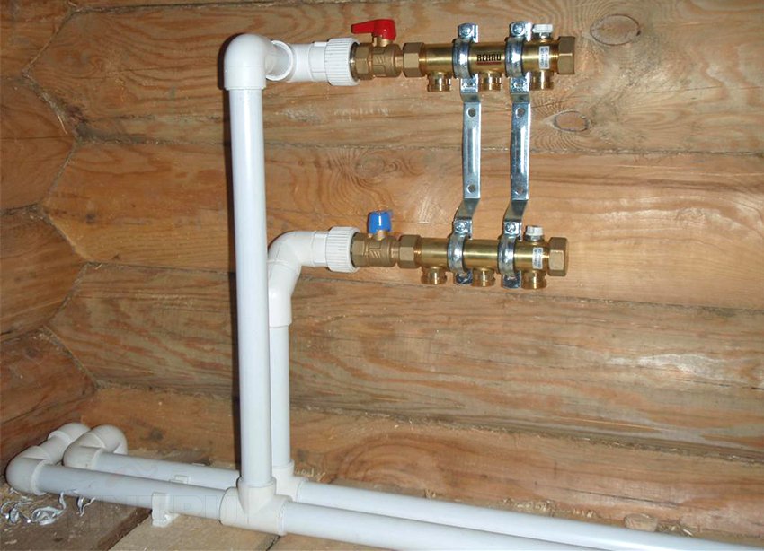
The second type of collectors has transparent flasks with floats for visually adjusting the flow rate. Heated floor pipes and wings are connected to such units of different lengths, instead of ball valves, a valve regulator is installed on each line.
Manifolds for heated floors can be supplied additional pump recycling and general thermostat. This is very typical for multi-storey buildings, for example, when combining underfloor heating with radiators on different floors. The base coolant temperature is 60-70 degrees, which is very high for a heated floor. Therefore, the pump mixes in some of the return water, reducing the floor heating to 35-40 °C.

The construction of decoupling on collectors is also convenient for maintenance. You do not have to stop the entire heating system in the event of a breakdown, since each section can be switched off and drained selectively.
Boiler room equipment
Typically, collectors for all floors are installed in the boiler room. This is convenient; the cost of an additional two dozen meters of pipes cannot be compared with organizing space for a separate collector unit, and they are quite cumbersome.
The boiler piping is classic: there are shut-off valves on the outlets, and a mud filter on the return connection. The pump is installed in the return gap and tied with a bypass. The membrane expansion tank is connected to an arbitrary point in the system, and the safety group is connected to a supply pipe a meter from the boiler.
 1 - boiler; 2 - security group; 3 - membrane expansion tank; 4 — heating radiators; 5 - shut-off valves; 6 - circulation pump with bypass; 7 - coarse filter
As always, it is recommended to piping boiler room equipment with steel pipes, which have a lower coefficient of linear expansion than plastic. Packaging on a polymer thread using an anaerobic sealant would be preferable.
All that remains to be done to the heating system is to add drainage and water injection pipes at the lowest point of the system. If there is a heated floor, a pair of collector outlets are allocated for this purpose: drainage is performed through the return, and purging is carried out through the supply.
Radiator piping
There are no special tricks in connecting radiators. As expected, a Mayevsky tap is screwed into one of the upper outlets; hot water can be supplied through the second.
However, the lower side pipe supply will be more aesthetically pleasing. The modern word in this regard is considered to be single-point connection devices, due to which it is possible to run both the supply and return into the same lower outlet of the radiator.

Using the same principle, you can make a point-to-point connection, but only on one side. This harness looks less cumbersome, plus there are many standard solutions. Typically, threaded connections on radiators are no more than one inch, so they can also be packaged using FUM tape.
The heating scheme for a two-story house with forced circulation is one of the components of the engineering project. The natural flow of coolant in such conditions is ineffective, since without a pump it is problematic to raise water to the second floor. The editors of Plumber Portal will tell you how the heating system of a two-story house works, and which wiring diagrams are the most effective.
From right organized system The heating of a two-story private house directly affects the comfort of living. This communication is designed to support optimal temperature, reducing heat loss and preserving the structure itself.
The center of the heating system in a two-story house is boiler, bringing the coolant to the optimal temperature. Based technical characteristics, the heat generator maintains the required temperature constantly. In modern private homes, almost all types of heating are used, and sometimes 2-3 types are combined together.
The boilers can operate on coke, coal, wood, diesel fuel, firewood, peat, pellets, natural gas and electricity. Fuel is selected based on its availability. More than 70% prefer gas boilers. A boiler powered by electricity (convector) is used as a backup or combined option; the boiler is included in the heating project for a two-story cottage in advance.
The boiler power depends on the coolant flow, which is determined by the internal radiator volume, the capacity of the heat exchanger and the filling of the pipeline sections.

Coolants in the heating system: water, antifreeze or electrolyte for flow-type electrode boilers. Water has more high heat capacity and density, but in winter period maintaining a constant room temperature is required. People who use their house irregularly in winter prefer to use antifreeze as a coolant.
Antifreeze, with its viscosity, expansion coefficient and heat capacity, slows down the heat transfer process and reduces heat removal from radiators. In the case of using “anti-freeze” as a coolant, it is necessary to increase the flow area of the system and the power of the pumps.
Important! If ethylene glycol is present in antifreeze, its use in boilers double-circuit type limited. Some additives destroy parts made of polypropylene, cast iron, non-ferrous metals and rubber.
Heating device is a steel, cast iron combined or anodized radiator, the task of which is to give off its heat, thereby providing optimal comfortable temperature. Heat transfer and inertia depend on the size and material from which the device is made.
The length of the radiator is changed by adjusting required quantity sections.
The required number of radiators (I) is calculated using the formula:
I=S*k1*k2*k3*k4*100/P (pieces), Where:
S - room area, (m2); P is the nameplate value of the power of one section, (W); k1 - increasing coefficient for double-glazed windows; k2 is the reduction coefficient of losses, which depends on the area of the external walls; k3 - dependent coefficient on the design and insulation of the roof (with or without an attic); k4 is a dependent coefficient on the ceiling height (k4 = 1, at h = 2.5 m), the higher the interfloor space, the greater the correction value.
Air vent(Maevsky tap) and thermostat valve are installed at the coolant inlet to the heating device to ensure uniform design heat removal. The shut-off valve is mounted on the outlet pipe and is needed for maintenance.
Piping(closed loop) ensures the tightness of the system. For the installation of heating systems in a private home, seamless and polypropylene pipes with minimal internal resistance.
The purpose of the pipeline is to distribute, transfer and return the coolant to the boiler. The flow movement can be slowed down by the roughness of the inner surface, changes in the diameters of the flow area, and turns. The method of circulation (natural or forced) is determined by the magnitude of the hydraulic resistance.
Additional elements of the heating system
Expansion tank closed or open heating systems are available in all types of private house junctions. The pressure created in the pipeline by the circulation pump or the force of gravity changes the boiling point of the coolant.
A spontaneous jump in pressure can provoke a sudden boiling of water, as well as the release of dissolved gases and a multiple increase in volume, which leads to the destruction of elements of the heating system. An expansion tank helps prevent such problems.
Installation shut-off valves in the heating system makes it possible to turn off a section of the system or equipment so that it is possible to carry out maintenance, repair or replacement. Ball valves are mounted on risers before and after pumps, manifolds, boilers and boilers.

TO safety fittings include check valve, safety valve, automatic air vent and balancing valve. Their task is to protect the pipeline from throttling flows and water hammer. The shut-off valve stops the fuel supply when the gas analyzer sensors are triggered, the power is turned off and circulation through the heat exchanger stops.
Control valves(electronic or electromechanical control valve, thermostat) should equalize the parameters in the heating system. The main condition for fittings and connecting parts in a heat supply system is that the fitting must ensure the passage of the coolant with minimal pressure losses and the tightness of branches, turns and diameter transitions.
Hydroarrow And distribution manifold reduce losses, separate hydraulic circuits, increase throughput and distribute the heat load. They also serve as a place for mounting measuring instruments responsible for safety (heat sensors, flow meters, pressure gauges, thermometers). The task of the thermodynamic switch is to ensure the removal of dissolved gases and suspended particles from the coolant.

The task circulation pump in the heating system is to ensure the flow of heated water in a closed loop, because of this, the height of the house does not affect the power of the pump. In “wet” circulation pumps, the rotor with impeller is located in the heating pipeline. As a lubricant and cooling of engine parts it is working environment. Working principle and functional features pumps depend on power, flow, efficiency and pressure.
The circulation pump is usually mounted on the return pipeline in front of the boiler or the pressure blower is placed on the bypass. Instructions for installation and operation of the device are developed by the manufacturer.
Features of a forced circulation system
Most modern heating systems can function at full capacity only if an individual artificial circulation, such that the coolant moves through the system due to the operation of the circulation pump.
To arrange forced circulation of heating in a two-story building, there are some prerequisites:
- installation of a pipeline with a smaller diameter, which facilitates the overall assembly of the wiring;
- providing zonal regulation (jointly or instead of general);
- the presence of 2nd and higher floors does not in any way affect heating;
- reducing the coolant temperature without changing heat transfer parameters;
- the ability to use inexpensive plastic pipes.
The disadvantages include the availability of power supply - interruptions are possible, but this can be easily avoided by using backup UPSs. The problem of louder noise can be solved by installing sound insulation in the boiler room.
Most suitable place inserting a circulation pump where the temperature drops to a minimum, that is, in front of the boiler on the return line.
The natural circulation pattern is an alternative option.
At the moment, autonomous heating systems with gravitational circulation, that is, operating on the basis of the natural laws of physics, are quite rare. The principle of operation is explained by the difference in density of cold and heated water and the presence of an additional control device - an expansion tank, mounted in the upper part of the hot water riser.
Network Feature natural type is an inclined position horizontal pipes(distribution and return) and the location of the boiler - it is mounted as low as possible. The coolant is supplied through the expansion riser, and the cooled water (or antifreeze) is discharged through the return riser.
If you think about how to properly heat a private house with your own hands, then remember that the advantages of the gravity circuit are independence from the power supply, ease of installation, and the absence of noise produced by the circulation pump. But it will be faster and more efficient to heat a large cottage with forced circulation wiring.
Single-pipe and two-pipe wiring diagrams
The choice of the type of heating and coolant wiring occurs during the development of the project.
A single-pipe heating system operates on the principle of sequential connection of radiators in the heating circuit wiring. The thermodynamics of the process is based on the increased diameter of the pipeline (not less than 32 mm), the slope of straight sections (0.5% of the length) and the excess of the radiator axis above the central line of the boiler (H).
Self-regulation in the circuit occurs due to the temperature difference between the first/last radiator and the force of gravity. The flow goes alternately through each heating device (the return of the previous radiator is the supply of the next one). The temperature decreases with distance from the heat source, and the density of water, on the contrary, increases.
Such wiring is usually used for systems with natural circulation. Scheme of a single-pipe heating system with open-type natural circulation, sample:

In a two-pipe heating system, the heating system is divided into a supply line and a return line. Distributing into two pipes increases the efficiency of the system, reduces heat losses and hydraulic resistance. A two-pipe circuit determines the parallel connection of the inlet and outlet pipes of the heating device. The temperature of the coolant in the radiators is equalized; distance from the heat source does not affect heating.
Two-pipe radial heating wiring diagram with a collector, photo:

Installation of thermostat valves and taps allows replacement or repair without shutting down the system. By adding a hydraulic module (arrow with coplanar manifold) to a two-pipe system, you can separate the radiator (high-pressure), underfloor heating (low-pressure) and hot water circuits. There are no disadvantages in the system with correct thermal engineering calculations.
Features of top and bottom feed
With a lower supply of coolant in the heating distribution diagram of a two-story house, it is assumed that heating risers are inserted into the ring of the first floor (basement and technical underground).
The distribution chain (supply) is laid together with the return ring. The coolant moves upward, passes through the radiators, and a collecting pipeline descends along the return risers, through which it returns to the boiler.
The supply risers are raised above the second floor radiators by combining by air line, which is equipped with an automatic valve to remove air from the system. Each heating device is equipped with a Mayevsky tap.
The upper wiring distinguishes the direction of movement of the working flow (from top to bottom). Main riser (pipe rising from the boiler, through interfloor ceilings into the central expansion tank) supplies the coolant to the ring or to the dead-end sections of the upper distribution.
Supply risers are lowered from the attic and fed into the radiators. hot water. Vertical risers collect the coolant into a return pipeline, which returns the coolant to the boiler.
Upper wiring is used in the southern regions of Russia. In the northern and central regions This method of supplying and distributing coolant requires the installation of a warm attic.
Vertical and horizontal wiring
Two-pipe vertical system (with both lower and the top way feed) requires constant balancing. When the adjustment conditions are met, it has hydraulic and temperature stability when the adjustment conditions are met.
Scheme of vertical wiring of the heating system of a two-story private house, example:

The basis of a horizontal two-pipe heating system for a two-story house is the manifold connection of heating radiators. The comb is located in a special factory-made cabinet. The polypropylene elements of the system are supplied by the manufacturer.
Thus, according to consultants, the site is the most efficient scheme heating a two-story house with forced circulation is a two-pipe system with a liquid coolant, equipped with a gas or electric boiler and a circulation pump.
Combined systems are more efficient; the selection of heat sources depends on the number of floors and the structure of the building itself. In any case, to create an individual scheme, it is recommended to consult with a specialist and make the final choice based on personal preferences. The price for his services is not so high, but the benefits are priceless.
Video example of organizing a heating system with a Tichelman loop: